Очень часто перед системным администратором стоит задача по объеденению в одну сеть 2 или более офисов находящихся в разных районах города, или вообще в разных городах, чтобы пользователи могли пользоваться общими ресурсами. Если не нужно шифровать данные(что в большинстве случаев так и есть), то наиболее оптимальным вариантом является объеденение двух точек через GRE туннель.
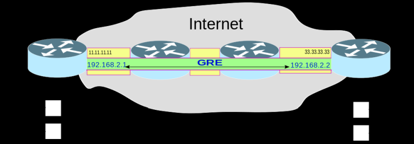
На рисунке показан пример работы GRE туннеля, между двумя маршрутизаторами A и B находится несколько маршрутизаторов, туннель позволяет обеспечить связь между сегментами сети 192.168.1.0/24 и 192.168.3.0/24 так, как если бы маршрутизаторы A и B были соединены прямым линком.
Для работы GRE туннеля оба маршрутизатора должены иметь внешние ip адреса на маршрутизаторе А это 11.11.11.11 на маршрутизаторе B 33.33.33.33 . Настройку маршрутизаторов А и В будем производить через консоль winbox.
На стройка маршрутизатора A
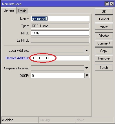
Создаем новый интерфейс для GRE, для этого заходим в панель interfaces, нажимаем на плюсик и выбираем GRE Tunnel. Указываем Remote Address, ip адрес маршрутизатора В, в нашем случае 33.33.33.33, все остальное оставим как есть.
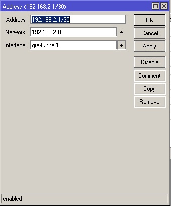
Затем идем в меню IP->Addresses, нажимаем на плюсик и в строке Address прописываем ip адрес для GRE интерфейса у нас он 192.168.2.1/30, этот адрес может быть любым, мы его сами назначаем для туннеля, в строке interface, из выпадающего списка, выбираем название нашего интерфейса созданного выше, в нашем случае это» gre-tunnel1″
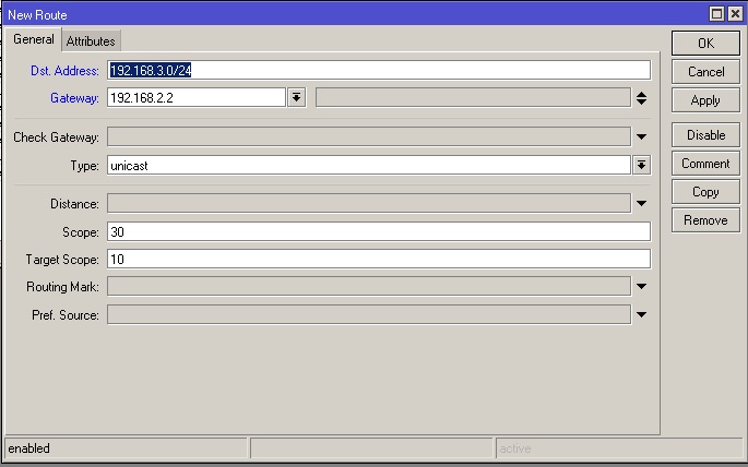
Заходим в меню IP->Routes нажимаем на плюсик и добавляем маршут до локальной сети маршрутизатора В, в строке DST.Address прописываем нашу удаленную сеть, которая настроена на маршрутизаторе В, у нас она 192.168.3.0/24, Gateway указываем ip адрес который мы назначили на GRE туннель на маршрутизаторе В, у нас это 192.168.2.2
Настройка маршрутизатора В
Маршрутизатор В настраивается зеркально маршрутизатору А.
1.Добавляем новый GRE интерфейс, в качестве Remote Address указываем внешний ip маршрутизатора А, у нас он 11.11.11.11
2.Прописываем на созданном GRE интерфейсе адрес, он должен быть в одной сети с адресом GRE интерфейса маршрутизатора А, у нас это 192.168.2.2
3.Прописываем новый маршрут, DST.Address указываем локальную сеть маршрутизатора А(у нас 192.168.1.1), а Gateway прописываем ip адрес на GRE интерфейсе маршрутизатора А(у нас 192.168.2.1).
После этих настроек компьютеры из локальной сети А должны «увидеть» компьютеры из локальной сети В. Это можно проверить командой ping.
Обучающий курс по настройке MikroTik
Нужно разобраться с MikroTik, но не определились с чего начать? В курсе «Настройка оборудования MikroTik» все по порядку. Подойдет и для начала работы с этим оборудованием, и для того, чтобы систематизировать знания. Это видеокурс из 162 уроков и 45 лабораторных работ, построен на официальной программе MTCNA. Проходить можно, когда удобно и пересматривать по необходимости – материалы курса выдаются бессрочно. Также есть 30 дней на личные консультации с автором. На пробу выдают 25 уроков бесплатно, заказать их можно на странице курса.
Если вы нашли ошибку, пожалуйста, выделите фрагмент текста и нажмите Ctrl+Enter.
VLAN (Virtual Local Area Network) is a logical topology that divides a single broadcast domain into multiple broadcast domains. It increases network security and performance as well as improves network efficiency. MikroTik VLAN routing configuration with manageable switch was discussed in previous article. Today we will learn how to configure VLAN between MikroTik RouterOS. This Router to router VLAN (layer3 VLAN) is useful when any ISP provide connection to one or more local ISPs who use MikroTik Router to maintain their LAN users.
Network Diagram
To configure VLAN between MikroTik RouterOS, I am following a network diagram like the below image.
Layer3 VLAN Routing Configuration
In this network, ether1 port of Core RouterOS is connected to internet having IP address 192.168.30.2/29. Ether2 port is connected to an Ethernet Hub. A hub is an OSI physical layer device. So, if there is a hub between Routers, then from Layer3 point of view it is the same as an Ethernet cable connection between them. Ether2 has two VLANs (VLAN 10 having IP address 172.22.2.1/30 and VLAN 20 having IP address 172.22.2.5/30).
Ether1 port of Client RouterOS1 is connected to the Ethernet Hub. This port has a VLAN interface whose id is 10. So, it is able to communicate with Core Router’s VLAN 10 interface with IP address 172.22.2.2/30. Ether2 port has a LAN having IP address 10.10.2.1/24.
Ether1 port of Client RouterO2 is also connected to the Ethernet Hub. This port has a VLAN interface whose id is 20. So, it is able to communicate with Core Router’s VLAN 20 interface with IP address 172.22.2.5/30. Ether2 port has a LAN having IP address 10.10.3.1/24.
As ether2 port of Core RouterOS and ether1 port of Client RouterOS1 and Client RouterPS2 are in the same broadcast domain, a VLAN configuration is so useful to optimize this network.
VLAN Configuration in Core RouterOS
Core RouterOS is connected to internet with ether1 port. So, ether1 port is working as WAN port. On the other hand, two client RouterOS is connected to ether2 port which is working as LAN port. As two client RouterOS are in the same broadcast domain, we will create two VLAN on LAN port to improve network efficiency. The following steps will show how to create VLAN in Core RouterOS and configure WAN and LAN properly.
Login to core MikroTik RouterOS using Winbox with full privilege credential.
Click on Interfaces menu item. Interface List window will appear. Click on VLAN tab and then click on PLUS SIGN (+). New Interface window will appear.
Put interface name (VLAN 10) in Name input box and put VLAN ID (10) in VLAN ID input box and choose your physical interface (ether2) that will be used as trunk port from Interface dropdown menu and then click on Apply and OK button. Similarly, create VLAN 20 interface.
Go to IP > Addresses menu item and click on PLUS SIGN (+). In New Address window, put WAN IP address (192.168.30.2/30) in Address input field and choose WAN interface (ether1) from Interface dropdown menu and then click on Apply and OK button.
Click on PLUS SIGN (+) again and put gateway IP of VLAN 10 (172.22.2.1/30) in Address input box and choose VLAN 10 interface from Interface dropdown menu and then click on Apply and OK button. Similarly, put VLAN 20 gateway IP (172.22.2.5/30) on VLAN 20 interface.
Go to IP > DNS and put DNS Server IP (8.8.8.8 or 8.8.4.4) in Servers input field and click on Apply and OK button.
Go to IP > Firewall and click on NAT tab and then click on PLUS SIGN (+). Inside General tab, choose srcnat from Chain dropdown menu and click on Action tab and then choose masqueradefrom Action dropdown menu. Click on Apply and OK button.
Go to IP > Routes and click on PLUS SIGN (+). In New Route window, click on Gateway input field and put WAN Gateway address (192.168.30.1) in Gateway input field and click on Apply and OK button.
VLAN configuration as well as basic RouterOS configuration in Core RouterOS has been completed. Now we will configure VLAN in Client RouterOS1 and Client RouterOS2.
VLAN Configuration in Client RouterOS1
Ether1 port of Client RouterOS1 is connected to Core RouterOS through Ethernet Hub and it is working as WAN port. As Core RouterOS is using VLAN for its client, Client RouterOS1 must create VLAN on its WAN interface. The following steps will show how to create VLAN in Client RouterOS1 and configure WAN and LAN properly.
Login to Client RouterOS1 using Winbox with full privilege credential.
Click on Interfaces menu item. Interface List window will appear. Click on VLAN tab and then click on PLUS SIGN (+). New Interface window will appear.
Put interface name (VLAN 10) in Name input box and put VLAN ID (10) in VLAN ID input box and choose your physical interface (ether1) from Interface dropdown menu and then click on Apply and OK button.
Go to IP > Addresses menu item and click on PLUS SIGN (+). In New Address window, put WAN IP address (172.22.2.2/30) in Address input field and choose VLAN interface (VALN 10) as WAN interface from Interface dropdown menu and then click on Apply and OK button.
Click on PLUS SIGN (+) again and put LAN gateway IP (10.10.2.1/24) in Address input box and choose ether2 interface from Interface dropdown menu and then click on Apply and OK button.
Go to IP > DNS and put DNS Server IP (8.8.8.8 or 8.8.4.4) in Servers input field and click on Apply and OK button.
Go to IP > Firewall and click on NAT tab and then click on PLUS SIGN (+). Inside General tab, choose srcnat from Chain dropdown menu and click on Action tab and then choose masqueradefrom Action dropdown menu. Click on Apply and OK button.
Go to IP > Routes and click on PLUS SIGN (+). In New Route window, click on Gateway input field and put WAN Gateway address (172.22.2.1) in Gateway input field and click on Apply and OK button.
Client RouterOS1 configuration with VLAN has been completed. Now it is able to communicate with internet as well as its LAN users are also able to get internet through this Router. For checking, assign a LAN IP in PC-2 and try to get internet. If everything is OK, PC-2 will be able to get internet.
VLAN Configuration in Client RouterOS2
Like client RouterOS1, ether1 port of Client RouterOS2 is also connected to Core RouterOS through Ethernet Hub and it is working as WAN port for this Router. As Core RouterOS is using VLAN for its client, Client RouterOS2 must create VLAN on its WAN interface too. The following steps will show how to create VLAN in Client RouterOS2 and configure WAN and LAN properly.
Login to Client RouterOS2 using Winbox with full privilege credential.
Click on Interfaces menu item. Interface List window will appear. Click on VLAN tab and then click on PLUS SIGN (+). New Interface window will appear.
Put interface name (VLAN 20) in Name input box and put VLAN ID (20) in VLAN ID input box and choose your physical interface (ether1) from Interface dropdown menu and then click on Apply and OK button.
Go to IP > Addresses menu item and click on PLUS SIGN (+). In New Address window, put WAN IP address (172.22.2.6/30) in Address input field and choose VLAN interface (VALN 20) as WAN interface from Interface dropdown menu and then click on Apply and OK button.
Click on PLUS SIGN (+) again and put LAN gateway IP (10.10.3.1/24) in Address input box and choose ether2 interface from Interface dropdown menu and then click on Apply and OK button.
Go to IP > DNS and put DNS Server IP (8.8.8.8 or 8.8.4.4) in Servers input field and click on Apply and OK button.
Go to IP > Firewall and click on NAT tab and then click on PLUS SIGN (+). Inside General tab, choose srcnat from Chain dropdown menu and click on Action tab and then choose masqueradefrom Action dropdown menu. Click on Apply and OK button.
Go to IP > Routes and click on PLUS SIGN (+). In New Route window, click on Gateway input field and put WAN Gateway address (172.22.2.5) in Gateway input field and click on Apply and OK button.
Client RouterOS2 configuration with VLAN has been completed. Now it is able to communicate with internet as well as its LAN users are also able to get internet through this Router. For checking, assign a LAN IP in PC-1 and try to get internet. If everything is OK, PC-1 will be able to get internet.
VLAN routing configuration between MikroTik RouterOS has been discussed in this article. I hope you will be able to create VLAN between RouterOS if your system requires. However, if you face any confusion to create a Layer3 VLAN between MikroTik RouterOS, feel free to discuss in comment or contact with me from Contact page. I will try my best to stay with you.
GNS3 is a network simulator software used by hundreds of thousands of network engineers worldwide to emulate, configure, test and troubleshoot virtual and real networks. GNS3 can talk a large number of network vendors including MikroTik. MikroTik introduces Cloud Hosted Router (a RouterOS version) that is used to run as virtual machine and a virtual machine can easily be integrated with GNS3. So, network administrators who are fond of MikroTik Router can now configure, test and troubleshoot their MikroTik network with GNS3 so easily. In my previous article I discussed how to install and configure GNS3 in Windows Operating System and in this article I will show how to integrate and configure MikroTik Router on GNS3 to simulate any MikroTik network.
MikroTik Router on GNS3
GNS3 is the best friend for those who are unable to arrange a lot of real devices and fail to configure, test and troubleshoot any complex network with MikroTik Router. GNS3 can now talk with MikroTik Router. So, emulating MikroTik Router on GNS3, a network administrator can easily do R&D and can implement it to production environment.
MikroTik Router integration and configuration on GNS3 can be divided into the following three steps.
Downloading MikroTik Cloud Hosted Router from MikroTik official website
Installing MikroTik Cloud Hosted Router on GNS3 and
Configuring a basic MikroTik network on GNS3.
Downloading MikroTik Cloud Hosted Router from MikroTik Official Website
MikroTik introduces Cloud Hosted Router (CHR) that can be used as a virtual machine on most of the popular hypervisors such as VMware, Hyper-V, Virtual Box, KVM as well as GNS3. So, we will download MikroTik CHR and integrate it in GNS3. The following steps will show how to download MikroTik CHR from MikroTik Official Website.
Go to MikroTik Official Website [mikrotik.com] from your favorite web browser and click on Software menu item. Software page will appear. Inside Software page, click on Download archive menu. Download archive page will appear where all current and historical MikroTikOS releases will be listed.
Expand any bugfix and stable release that you like. You will find four CHR files are available here. Among these, click on chr-version.img.zip file (such as chr-6.40.9.img.zip).
In a few seconds, your download will be started and within a few minutes your download will be completed.
Go to your download location and unzip the downloaded zip file. You will find a (.img) [chr-6.40.9.img] file now.
MikroTik CHR is now in your Desktop. In the next step, we will install MikroTik Router on GNS3 using this Cloud Hosted Router.
Installing MikroTik Cloud Hosted Router on GNS3
After downloading MikroTik Cloud Hosted Router (CHR image file) from MikroTik official website, it is time to install it on GNS3. The following steps will show how to install MikroTik Cloud Hosted Router on GNS3 as QEMU VM.
Run GNS3 and go to Edit > Preferences. Preferences window will appear.
Inside Preferences window, Click on Qemu VMS from left panel. Qemu VM templates panel will appear at the right side.
Inside Qemu VM templates, click on New button. You may find a warning message about The recommended way to run QEMU on Windows and OSX is to use the GNS3 VM. As we are not using GNS3 VM, just click OK button. New QEMU VM template window will appear.
New QEMU VM template window will ask to provide a name for the new virtual machine. Put a suitable name (example: MikroTik-6.40.9) in Name input field and then click on Next button.
New QEMU VM template window will ask to adjust virtual machine RAM. By default it is assigned 256MB that is enough for a test MikroTik Router. If you wish you can increase RAM size by editing RAM input filed. Click on Next button now.
New QEMU VM template window will ask to choose Console type. Among three console type, choose telnet from dropdown menu and click on Next button.
New QEMU VM template window will ask to choose Disk image for this virtual machine. Click on Browse button and choose your downloaded CHR image file. Now it will ask whether you want to copy this image file to default images directory or not. Click on Yes button and then click on Finish button.
Now you will find newly created MikroTik VM in Qemu VM templates panel. Click on Edit button. QEMU VM configuration window will appear.
Inside QEMU VM configuration window, click on Network tab. By default one network adapter is assigned for a new virtual machine. But our MikroTik Router requires minimum two network adapters. So, change Adapters value one to two and then click on OK button.
Click Apply and OK button to save new MikroTik QEMU VM.
A new appliance named MikroTik-6.40.9 (according to your provided name) will now be available in appliance list. Click on Brose all devices button from devices toolbar and choose installed appliances and you will find your new MikroTik appliance is available here.
We have successfully integrated MikroTik Router on GNS3. Now it is time to configure and test our integrated MikroTik Router by designing and configuring a basic network on GNS3.
Configuring a Basic MikroTik Network on GNS3
After installing MikroTik Router on GNS3, it is time to configure a basic MikroTik network on GNS3 and test whether it is able to talk with the real network or not. Complete network configuration on GNS3 with MikroTik Router can be divided into two parts.
Designing a basic MikroTik network on GNS3 and
Configuring the network devices to talk with real network.
Designing a Basic MikroTik Network on GNS3
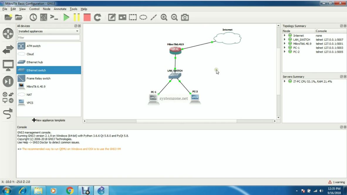
Before going to start MikroTik Router configuration, we first need to design a MikroTik network on GNS3. In this article, we will configure a basic network that looks like to the below image.
Basic Mikrotik Network on GNS3
In this network diagram, MikroTik Router’s ether1 port is connected to internet cloud which is also connected to the public network. On the other hand, MikroTik Router’s ether2 port is connected to an Ethernet Switch and two VPCSs are connected to this Switch. We will now configure this network so that MikroTik Router as well as two VPCSs is able to communicate with the public network. So, design this MikroTik network on GNS3 and follow the below section to configure it. If you face any difficulty to design this network on GNS3, feel free to visit my previous article about GNS3 installation and configuration where I have discussed how to design networks on GNS3.
Configuring GNS3 Network Devices to Talk with the Real Network
In the above network diagram, there are five network appliances. Among these Ethernet Switch is a plug and play device. So, there is no configuration for LAN Switch. But we have to configure Internet Cloud, MikroTik Router and two VPCS.
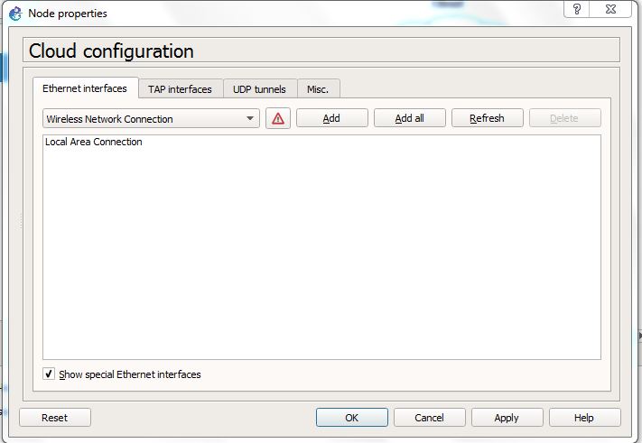
Cloud Configuration
Cloud is the virtual internet POP in GNS3. So, it has to connect to any real network adapter. Click mouse Right Button on the cloud icon and click on Configure option. Node properties window will appear. Inside this window, click on Ethernet interfaces tab. Inside Ethernet interfaces tab, choose your desired network adapter that you want to bind with this Cloud from dropdown menu and then click on Add button. (If you don’t find your desired network adapter in dropdown menu, click on Show special Ethernet interfaces checkbox and you will find that your desired network adapter will now be available in interface dropdown menu). Your added network adapter will be listed in the Ethernet interfaces box area. Now click Apply and OK button.
MikroTik Router Configuration
We will just do some basic configurations in MikroTik Router. Basic MikroTik Router configuration includes assigning WAN IP, LAN IP, DNS IP as well as Route and NAT configuration. The following steps will show how to perform these tasks on MikroTik Router.
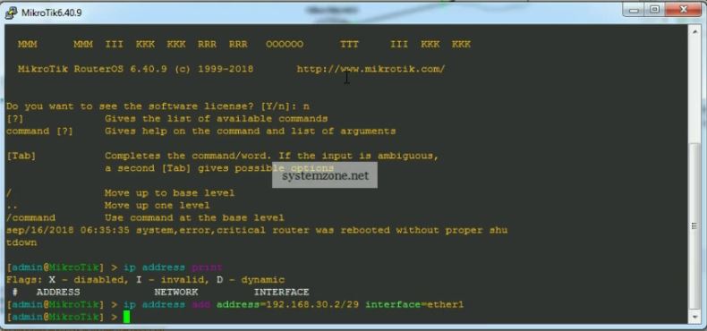
Click mouse right button on MikroTik Router icon and click on Start option to start MikroTik Router. Again click mouse right button and click on Console option. Putty command prompt will appear that will ask for login. Provide MikroTik login value ‘admin’ and keep password blank. Now MikroTik command prompt will appear.
Integrated MikroTik Router has two interfaces (ether1 and ether2). We will assign WAN IP (192.168.30.2/29) on ether1 interface and LAN IP (10.10.200.1/24) on ether2 interface. So, issue below command to assign WAN IP on ether1 interface.
ip address add address=192.168.30.2/29 interface=ether1
Collect a PC where MikroTik WAN IP is accessible and download Winbox from MikroTik official website.
Open Winbox and put MikroTik WAN IP in Connect To input box and put ‘admin’ in Login input box and keep Password field blank and then click on Connect button. Winbox will now connect with MikroTik Router.
Go to IP > Addresses menu item. Address List window will appear and you will find your assigned WAN IP is listed here.
Click on PLUS SIGN (+) and put LAN IP (10.10.200.1/24) in Address input field and choose LAN interface (ether2) from Interface dropdown menu and click on Apply and OK button.
Go to IP > DNS and put DNS servers IP (8.8.8.8 or 8.8.4.4) in Servers input field and click on Apply and OK button.
Go to IP > Firewall and click on NAT tab and then click on PLUS SIGN (+). Under General tab, choose srcnat from Chain dropdown menu and click on Action tab and then choose masqueradefrom Action dropdown menu. Click on Apply and OK button.
Go to IP > Routes and click on PLUS SIGN (+). In New Route window, click on Gateway input field and put WAN Gateway address (192.168.30.1) in Gateway input field and click on Apply and OK button.
MikroTik Putty Command Prompt
MikroTik Router has been completed. MikroTik Router is now ready to communicate with the public network. Test with ping command from MikroTik terminal. If everything is OK, you will get result.
Assigning LAN IP in GNS3 VPCS VPCS is a PC simulator that helps to test network configuration with ping and trace route. VPCS supports either DHCP or static IP. In this article, we will assign static LAN IP in our VPCSs (PC-1 and PC-2) and test whether it can communicate with the real network or not.
Assigning Static LAN IP in PC-1 The following steps will show how to assign static IP address in PC-1.
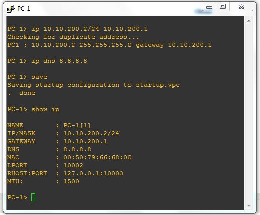
Click mouse right button on PC-1 icon and then click on Console option. PC-1 command prompt will appear.
Issue ip command in PC-1 terminal with this format:[ip ip_address/netmask gateway] example: ip 10.10.200.2/24 10.10.200.1
To set DNS, issue dns command with ip command: [ip dns dns_server_ip] example: ip dns 8.8.8.8
To save this IP configuration, issue save command.
To show IP configuration, run show ip command.
PC-1 Terminal
Now ping to gateway or any public domain or trace route with trace command. If everything is OK, PC-1 will be able to ping and trace route to real networks.
Assigning Static LAN IP in PC-2 The following steps will show how to assign static IP address in PC-2.
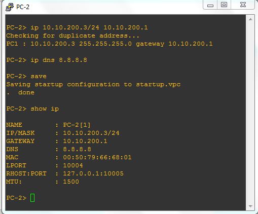
Click mouse right button on PC-2 icon and then click on Console option. PC-2 command prompt will appear.
Issue ip command in PC-2 terminal with this format:[ip ip_address/netmask gateway] example: ip 10.10.200.3/24 10.10.200.1
To set DNS, issue dns command with ip command: [ip dns dns_server_ip] example: ip dns 8.8.8.8
To save this IP configuration, issue save command.
To show IP configuration, run show ip command.
PC-2 Terminal
Now ping to gateway or any public domain or trace route with trace command. If everything is OK, PC-2 will be able to ping and trace route to real networks.
How to integrate and configure MikroTik Router on GNS3 has been discussed in this article. I hope you will now be able to design any MikroTik network on GNS3 for R&D purpose. However, if you face any confusion, feel free to discuss in comment or contact with me from Contact page. I will try my best to stay with you.
Создание сертификатов и ключей подписи для сервера и клиента
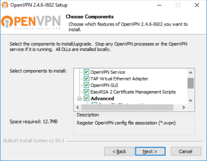
Сертификаты будем создавать на машине c win10. Скачиваем сам OpenVPN (в моем случае это версия 2.4.6) для генерации сертификатов.
Важно, при установке выбрать все галочки.
Открываем папку “C:Program filesOpenVPNeasy-rsa“, запускаем init-config.bat, появится файл vars.bat.sample, открываем его и редактируем такие строки:
set KEY_COUNTRY=BY

set KEY_PROVINCE=GomelRegion

set KEY_CITY=Gomel

set KEY_ORG=VTelecom

set KEY_EMAIL=disnetern@disnetern.ru

set KEY_CN=server

set KEY_NAME=server

set KEY_OU=disnetern
Эти параметры оставить неизменными “Key_CN” и “Key_NAME”, остальные можно вписать произвольно. Сохраняем как vars.bat в сваю домашнюю папку (в текущую не разрешат права), а потом перемещаем этот файл в “C:Program filesOpenVPNeasy-rsa” с подтверждением замены.
Теперь открываем openssl-1.0.0.cnf и выставляем параметр default_days=3650 (3650= это 10 лет, можете выставить нужное время истекания сертификата по своему усмотрению ).
Теперь открываем CMD от имени администратора и пишем поочередно команды:
cd C:Program FilesOpenVPNeasy-rsa

vars.bat

clean-all.bat
«Скопировано файлов: 1». Значит, процедура успешна. Если выдало сообщение ” vars.bat не является внутренней или внешней командой, исполняемой программой или пакетным файлом.” То отредактируйте в этом файле правильные, полные пути до команды.
Далее поочередно вбиваем команды для создания ключей:
build-dh

build-ca
Если опять выдало сообщение об ошибке – редактируем полный путь до команды openssl. (В моем случает нужно было указать полный адрес с пробелом, указав его в двойных кавычках). Все вопросы подтверждаем Enter. Дальше набираем:
build-key-server server
Все вопросы подтверждаем Enter, а на последние два соглашаемся “Y”
Далее создаем сертификат клиента:
build-key client
При ошибке, редактируем путь. На вопрос Common Name – ввести client. В конце два раза подтвердить “Y”.
С сертификатами готово. Забираем их из папки C:Program FilesOpenVPNeasy-rsakeys : ca.crt, server.crt, server.key
Настройка сервера OpenVPN на mikrotik
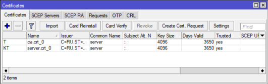
Заливаем файлы сертификатов и ключа на роутер Mikrotik, где будем настраивать сервер.
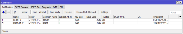
Далее произведём импорт сертификатов, System – Certificates, выбираем поочередно сертификаты из списка ca.crt, server.crt, server.key и жмём кнопку Import:
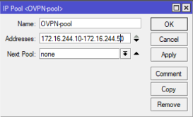
Создаём новый пул IP адресов для наших клиентов OpenVPN. IP -> Pool, добавили диапазон, например, 172.16.244.10-172.16.244.50, и назвал пул OVPN-pool
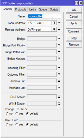
Далее создаём PPP профиль. PPP -> Profiles-> вводим имя профиля, локальный адрес роутера, в моем случае 172.16.244.1, с созданным пулом адресов OVPN-pool, остальные настройки выставляем по желанию.
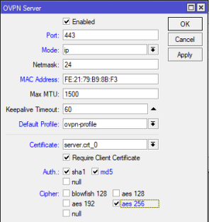
Далее настраиваем сам OpenVPN сервер, PPP->Interface->OVPN Server, ставим Enabled, выбираем нужный порт, mode выставляем ip, выбираем созданный ранее профиль, ставим Require Client Certificate и выбираем сертификат server, остальные параметры по желанию.
Создадим пользователя, переходим в раздел PPP -> Secrets, вводим имя пользователя, пароль, указываем сервис и профиль.
Так как используются сертификаты, необходимо что бы время на сервере и на клиенте совпадало, для этого настраиваем ntp клиент и временную зону на роутере в разделе- System ->Clock/NTP Client. Адреса для NTP клиента можно взять, например, здесь.
Еще не забудьте настроить Ваш фаерфол для разрешения порта для OVPN, IP -> Firewall->Filter Rules
Теперь можно подключаться к нашему OVPN серверу.
Настройка Mikrotik в качестве клиента OpenVPN сервера
Сначала необходимо добавить сертификаты клиента на роутер (client.crt и client.key). Не передавайте никому закрытый ключ сертификата – “ca.key”, имея его можно создавать сертификаты подписанные данным ключом.
Делаем импорт сертификатов, идём в раздел System – Certificates, выбираем поочередно сертификаты client.crt->client.key.
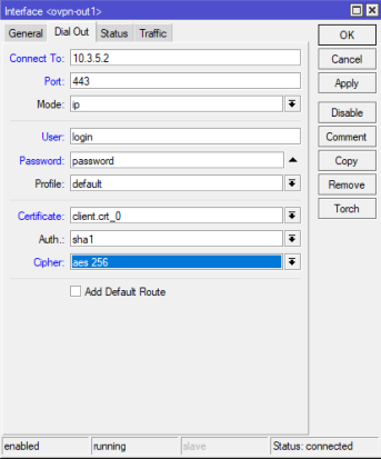
Само соединение OpenVPN настраивается в меню PPP-> добавить OVPN Client
Указываем адрес сервера, логин/пароль, порт, клиентский сертификат и тип шифрования:
GNS3 (Graphical Network Simulator) is one of the most popular network simulator software used by hundreds of thousands of network engineers worldwide to emulate, configure, test and troubleshoot virtual and real networks. GNS3 supports a large number of vendors such as MikroTik, Cisco, Juniper, Windows, Linux and many other vendors. GNS3 can be installed on Windows, Linux and MAC Operating System. In this article, I will show how to download and install GNS3 application in Windows Operating System. I will also show how to configure a basic network in GNS3 that will communicate with the real networks.
GNS3 Download for Windows Operating System
GNS3 is completely free and open source software. So, it can be downloaded from its official website without any charge. In GNS3 official website, the installation file is found for major three operating platforms (Windows, Linux and MAC). The following steps will show how to download GNS3 installation file (.exe) for Windows Operating System.
Go to GNS3 official website (gns3.com) from your favorite web browser.
You must Sign Up and Login before any download. So, Sign Up and Login with your personal information.
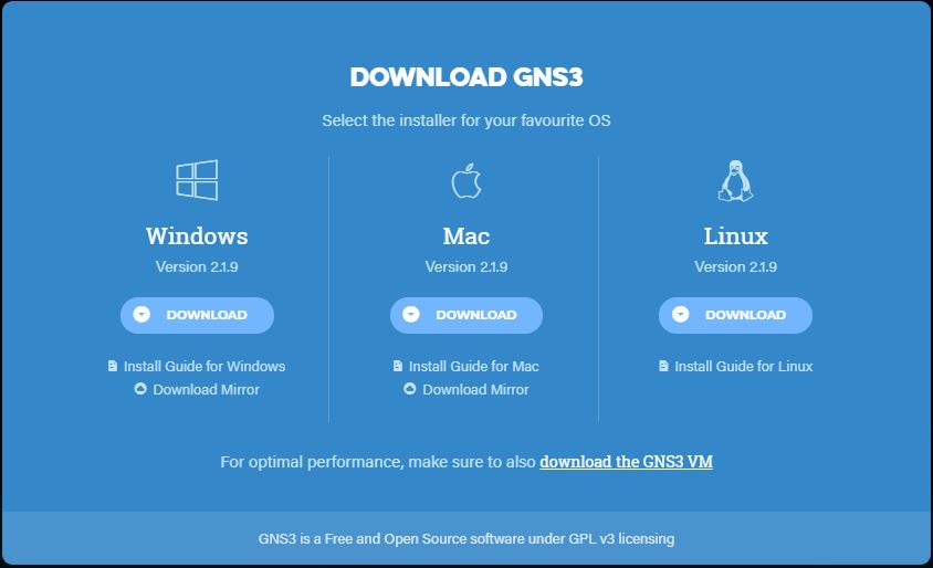
Now click on DOWNLOAD menu item. GNS3 current version (now it is 2.1.9) information will appear with a download button. Click on this Download button. GNS3 download pop up window will appear where installer file for major three operating systems will be found.
Click on Download button under Window operating system. Within a few seconds your download will be started. The installer file (GNS3-2.1.9-all-in-one.exe) size is about 54.5 MB.
GNS3 Download Popup Window
GNS3 Installation Step by Step on Windows Operating System
After completing GNS3 installer file download, we will now start installation on Windows Operating System. But before going to start installation, we have to check system requirements. For GNS3 v2.1.9, we have to use minimum Windows 7 SP1 (64 bit), 4GB RAM and IGB free storage. To get detail about GNS3 installation requirements, visit GNS3 installation minimum, recommended and optimal requirements page.
The following steps will show how to install GNS3 on Windows Operating System.
Click twice on your downloaded GNS3 Windows installer file (GNS3-2.1.9-all-in-one.exe). A security warning window will appear. Inside this window, click on Run button.
GNS3-2.1.9 Setup starting window will appear to welcome you. Nothing to do in this window. Just click on Next button.
License Agreement window will appear. Accept the license agreement clicking the I Agree button.
Choose Start Menu Folder window will appear. Keep default name (GNS3) or if you wish you can change it. Click on Next button.
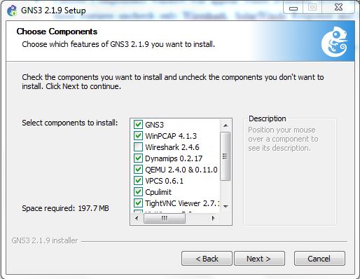
Choose Components window will appear where available GNS3 features will be listed. Among these features uncheck only Wireshark, SolarWinds Response and Npcap features because initially we don’t require these features. Now click Next button.
GNS3 Features List
Choose Install Location window will appear. Keep default location or if you wish you can change browsing destination folder. Now click Install button.
GNS3 features installation will be started and installation progress will be found on progress bar. During GNS3 installation, WinPCAP installation will be appeared separately. Follow some easy instructions as indicated. Also keep your internet connection OK because virt-viewer will be downloaded during GNS3 installation.
Within a few minutes, GNS3 installation will be completed and Installation Complete window will appear with success message. Click Next button from this window.
Solarwinds Standards Toolset window will appear. We don’t need any toolset now. So, click on No radio button and then click on Next button.
GNS3 Setup close window will appear. Click Finish button. GNS3 installation will be finished and GNS3 will start to run now.
Introduction to GNS3 GUI
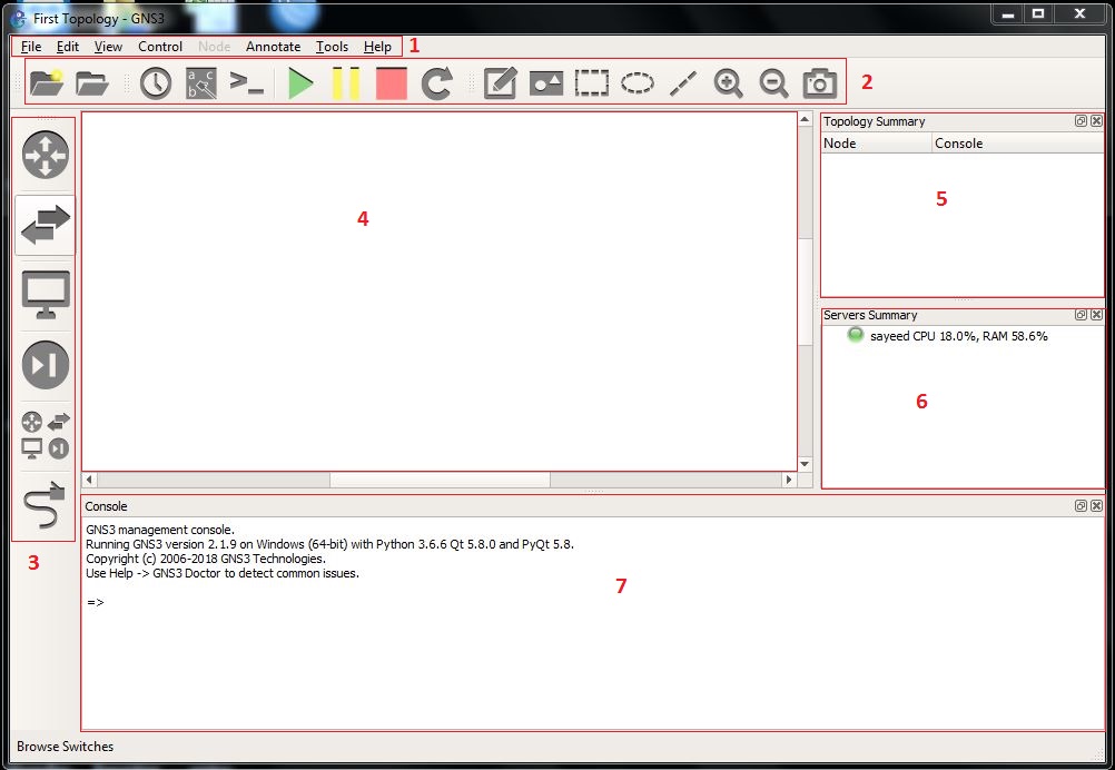
After completing GNS3 installation, you will find GNS3 shortcut icon in your Desktop. GNS3 icon can also be found in Windows Start menu. Run GNS3 from Desktop or Start menu. You will find GNS3 GUI like below image.
GNS3 GUI
The GNS3 GUI is subdivided into several sections. These are the Menubar, Toolbar, Device Toolbar, Workspace, Topology Summery, Servers Summery and the Console section.
GNS3 Menubar
The GNS3 Menubar ((labeled 1)) found at the top of the GNS3 GUI that contains several menu items which are frequently required to manage GNS3 GUI. Each menu item contains several options such as New blank project, Open project, Import appliance, Preference, Setup Wizard and so on.
GNS3 Toolbar
The GNS3 Toolbar (labeled 2) is located below the Menubar. It contains groups of icons that allow you to easily perform common tasks.
Device Toolbar
The GNS3 Device Toolbar (labeled 3) is categorized by network devices such as Routers, Switches, End Devices, Security, All Devices, along with the Add a Link button at the bottom that looks like a network cable.
GNS3 Workspace
The GNS3 Workspace (labeled 4) is where network devices will be dragged and dropped from Device Toolbar in order to build our topology.
Topology Summery
The Topology Summery panel (labeled 5) will display the current devices in the GNS3 Workspace, their status (on/off/suspended), as well as which devices are connected to one another.
Servers Summery
The Servers Summery panel (labeled 6) will display the servers in use (local GNS3, local GNS3 VM, and remote GNS3 VM), their status (on/off) and their current resource usage.
GNS3 Console
The GNS3 Console panel (labeled 7) will display any errors or any issues GNS3 itself encounters, and will output those messages in this panel.
First Topology with GNS3
After installing GNS3, it is time to simulate and study our desired network. Now we will design a basic network in GNS3 that will communicate with real network. Our basic network is placed in GNS3 workspace like the below image.
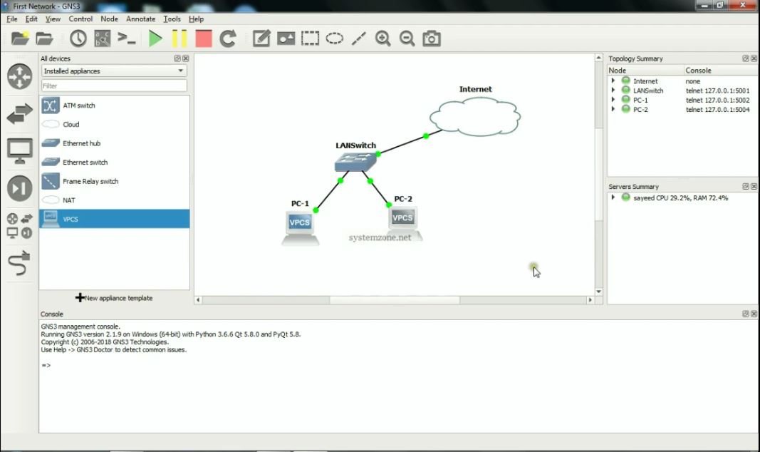
First Topology on GNS3
In this basic network, we have an internet cloud which is connected to GNS3 server’s network adapter. So, any device connected to this cloud will be able to connect to real network. We also have an Ethernet switch connected to the internet cloud and two VPCSs connected to the Ethernet switch . Virtual PC Simulator (VPCS) is a program that allows you to simulate a PC supporting DHCP and ping. So, we can easily test and study our network configuration using VPCS.
We will now design this basic network in our GNS3 GUI. So, run GNS3 GUI from Windows Start Menu or Desktop and follow the below steps to design this network in GNS3.
Go to File menu and click on New blank project item. Project window will appear. Inside Project window, put a project name in Name input field and then click OK button.
Now click on Browse all devices button from Device Toolbar. All devices panel will appear at right side. Inside this panel you will find Installed and available appliances for GNS3. Choose only Installed appliances from drop down menu. A few installed appliances will be found inside this panel.
Drag and Drop the Cloud appliance to GNS3 Workspace and place it according to above network diagram. If you wish you can rename it as you like clicking twice on the appliance name.
Right click on the cloud icon and click on Configure option. Node properties window will appear. Inside this window, click on Ethernet interfaces tab. Inside Ethernet interfaces tab, choose your desired network adapter that you want to bind with this cloud from dropdown menu and then click on Add button. (If you don’t find your desired network adapter in dropdown menu, click on Show special Ethernet interfaces checkbox and you will find that your desired network adapter will now be available in interface dropdown menu). Your added network adapter will be listed in the Ethernet interfaces box area. Now click Apply and OK button.
GNS3 Cloud Configuration
Again Drag and Drop an Ethernet Switch and Two VPCSs in GNS3 Workspace and place them according to the above network diagram.
You will find status (on/off) of your devices in Topology summery panel. If your device is on, it will turn into green light otherwise it will be red.
Now click on Add a link button from Device Toolbar and move to Workspace. Mouse icon will turn into PLUS SIGN (+). Click on Cloud icon and it will ask to choose a network adapter showing the available network adapters. Click on your desired network adapter and move mouse to switch icon and click on it. It will also ask to choose an Ethernet port showing all available Ethernet ports. Click on an Ethernet port which you want to connect to internet. Now you will find a link is established between switch and internet cloud indicating green light signs that mean both devices are up and running and ready to communicate with each other.
Similarly, connect both VPCS and Switch and then click on Add a link button again so that mouse icon shows normally in Workspace. You will find VPCS is indicating red light because VPCS is by default in off state. Start VPCS by clicking mouse right button on it and choosing Start option. Now you will find the red light will turn into green.
Our first network in GNS3 is ready. Now we will assign our LAN IP in PC-1 and PC-2 so that it can communicate to our real LAN devices as well as to WAN networks.
Assigning IP in GNS3 VPCS
VPCS is a PC simulator that helps to test network configuration with ping and trace route. VPCS supports either DHCP or static IP. In this article, we will assign static IP in our VPCSs (PC-1 and PC-2) and test whether it can communicate with real network or not.
Assign Static IP in PC-1
The following steps will show how to assign static IP address in PC-1.
Click mouse right button on PC-1 icon and then click on Console option. PC-1 command prompt will appear.
Issue ip command in PC-1 terminal with this format:[ip ip_address/netmask gateway] example: ip 10.10.200.2/24 10.10.200.1
To set DNS, issue dns command with ip command: [ip dns dns_ser_ip] example: ip dns 8.8.8.8
To save this IP configuration, issue save command.
If you have misconfigured the IP settings, issue clear ip command to clear IP settings.
To show IP configuration, run show ip command.
PC-1 Terminal
Now ping to gateway or any public domain or trace route with trace command. If everything is OK, PC-1 will be able to ping and trace route to real networks.
Assign Static IP in PC-2
The following steps will show how to assign static IP address in PC-2.
Click mouse right button on PC-2 icon and then click on Console option. PC-2 command prompt will appear.
Issue ip command in PC-2 terminal with this format:[ip ip_address/netmask gateway] example: ip 10.10.200.3/24 10.10.200.1
To set DNS, issue dns command with ip command: [ip dns dns_ser_ip] example: ip dns 8.8.8.8
To save this IP configuration, issue save command.
If you have misconfigured the IP settings, issue clear ip command to clear IP settings.
To show IP configuration, run show ip command.
PC-2 Terminal
Now ping to gateway or any public domain or trace route with trace command. If everything is OK, PC-2 will be able to ping and trace route to real networks.
This is the starting with GNS3 application. In future we will learn more complex appliance and network in GNS3 application.
GNS3 download, installation and configuration in Windows Operating System has been discussed in this article. I hope you will now be able to install and configure GNS3 successfully in your Windows OS. However, if you face any confusion to install and configure GNS3 in Window OS, feel free to discuss in comment or contact with me Contact page. I will try my best to stay with you.
MikroTik RouterOS is in constant development and new features or bug fixes are frequently available, sometimes even monthly. So, it is always recommend upgrading your MikroTik RouterOS to a latest and stable version before beginning any configuration. Sometimes you may find that your production router is required to be upgraded to a new version based on some logical reasons such as:
A new feature is available to a new update and you need to implement that new feature.
New version has solved any security vulnerability that old version suffers.
New version provides any bug fix that you need.
If don’t find these valid reasons, keep away from upgrading your MikroTik RouterOS. But if these are your valid reasons, upgrade your RouterOS as soon as possible without any hesitation. In this article I will show how to easily upgrade MikroTik RouterOS and RouterBOARD firmware using Winbox.
How to Upgrade MikroTik RouterOS using Winbox
Winbox provides an easy graphical way to upgrade MikroTik RouterOS. Using Winbox MikroTik RouterOS can be upgraded according to the following two demands.
Upgrading MikroTik RouterOS to a specific version
Upgrading MikroTik RouterOS to the latest version
Upgrading MikroTik RouterOS to a Specific Version
Sometimes you may find that a specific RouterOS version is more stable than the current or latest bug fixed version. In this case, you will prefer to upgrade your RouterOS to this specific version. The following steps will show how to upgrade your RouterOS to a specific version.
Login Mikrotik Router with Winbox Software.
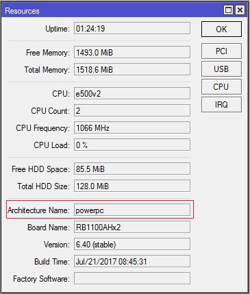
From Winbox, go to System > Resources menu item and find Architecture Name from Resources window.
MikroTik Router Resources Window
Now go to MikroTik download archive page [mikrotik.com/download/archive] and find your specific RouterOS version and then click on it. Now download (.npk) file [routeros-architecture_name-routeros_version.npk] from this RouterOS release list.
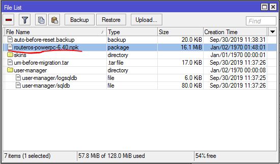
Inside Winbox, click on the Files button. File List window will appear now.
Upload your downloaded (.npk) file to this File List window by drag and drop.
File List Window
Once the file has completely uploaded, issue a reboot command by clicking System and Reboot.
After a few minutes, your router will return to operation with the new version installed. You can confirm that your RouterOS has been updated to latest version visiting System and Packages and then checking Package version within Package List window.
Upgrading MikroTik RouterOS to Latest Version
If you wish to update your RouterOS to latest stable version, no need to follow the above manual option. MikroTik provides another easier and automatic method to update RouterOS to the latest version using Winbox. The follow steps will show how to update MikroTik RouterOS to the latest version automatically using Winbox.
Inside Winbox, go to System > Packages menu item. Package List window will appear.
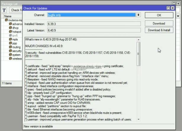
Inside Package List window, you will find Check For Updates button. Click on it. Check For Updates window will appear.
Inside Check For Update window, choose bugfix only from Channel dropdown menu. Now you will find your installed RouterOS version and the latest bugfix version in Installed Version and Latest Version input box respectively.
Check For Updates Window
Now click on Download button. Within few minutes latest RouterOS version will be downloaded.
After completing download, issue a reboot command by clicking System and Reboot.
After a few minutes, your router will return to operation with the new version installed. You can confirm your update to latest version visiting System and Packages and then checking Package version within Package List window.
Upgrading MikroTik RouterBOARD Firmware
Once the MikroTik RouterOS has been upgraded, it is advisable to update the firmware (boot loader) if you use MikroTik RouterBOARD. The following steps will show how to update MikroTik RouterBOARD firmware using Winbox.
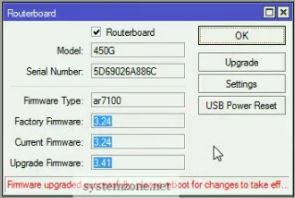
Inside Winbox, go to System > Routerboard menu item. Routerboard popup window will appear.
Inside this Routerboard popup window, you will find factory firmware, current firmware and upgrade firmware.
Click on Upgrade button. RouterOS will now ask for upgrade confirmation, click on Yes button.
Within a few seconds, upgraded firmware will be downloaded and RouterOS will ask to reboot to take upgrade effect.
Firmware Update Window
Issue a reboot command by clicking System and Reboot.
After a few minutes, your router will return to operation with the new firmware installed. You can confirm firmware upgrade information visiting System and Routerboard menu.f
If you face any confusion to follow above steps properly, watch the below video about Upgrading MikroTik RouterOS and Firmware carefully. I hope it will reduce your any confusion.
How to upgrade MikroTik RouterOS and Firmware has been discussed in this article. I hope you will now be able to update your RouterOS and Firmware successfully following the above steps properly. However, if you face any confusion to upgrade your RouterOS and Firmware, feel free to discuss in comment or contact with me from Contact page. I will try my best to stay with you.