MikroTik Wiki and Forum say that there is no way to recover MikroTik user password without losing MikroTik configuration. But if you have an unencrypted configuration file backup taken before, you will be able to recover your user password using MikroTik password recovery tools. How to Backup and Restore MikroTik configuration file manually was discussed in my previous article. I also discussed how to backup MikroTik configuration file automatically via Mail in another article and in this article I will show how to recover forgotten user password using MikroTik configuration file backup.
Recover MikroTik User Password using Configuration File Backup
If you have a practice to store MikroTik configuration file backup regularly, you will be able to recover your MikroTik user password if you forget unfortunately. There are two methods to recover MikroTik user password from unencrypted configuration file backup.
Recover MikroTik password using online password recovery tool
Recover MikroTik password using Linux password recovery tool
Recover MikroTik Password using Online Password Recovery Tool
If you have an unencrypted backup file, you can easily recover your user password using MikroTik Password Recovery Online Tool. The following steps will show how to recover MikroTik user password using online password recovery tool.
Go to MikroTik Password Recovery Online Tool [mikrotikpasswordrecovery.net].
Upload your unencrypted backup file using Choose File button.
Put provided captcha for security purpose.
Click on Upload and show me passwords button and you will find your username and password list within a textarea.
Recover MikroTik Password using Linux Password Recovery Tool
If you face any problem to use Online Password Recovery Tool or like to use Linux command rather than online tool, you can use MikroTik Password Recovery Tool in Linux. If you are a new Linux user, follow my article about how to setup CentOS Linux and how to configure CentOS network and then continue this article. The following steps will show how to use Linux password recovery tool to recover MikroTik’s forgotten user password.
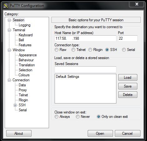
Login to your CentOS Linux operating system with root user using Putty or SSH Secure Shell Client.
Install wget and openssl-devel packages if not installed before with yum command [yum install wget openssl-devel -y]. It will be also better to update your operating system with update command [yum update] if you face any problem to run Linux password recovery tool.
Create a temporary folder [mkdir /temp] in root directory and go to this directory with cd command [cd /temp].
Go to [manio.skyboo.net/mikrotik] and download latest mtpass released package and store this package in temp folder. Alternately, you can run wget command to download this package [wget http://manio.skyboo.net/mikrotik/mtpass-0.9.tar.bz2].
Extract this downloaded package with tar command [tar jxvf mtpass-0.9.tar.bz2].
Now go to mtpass extracted folder [cd mtpass-0.9] and then run make command [make] to compile this package.
Now upload your unencrypted backup file (MikroTikBackup.backup) into temp folder and run this command [./mtpass /temp/MikroTikBackup.backup]. If everything is OK, you will find your MikroTik user name and password.
Complete CentOS Linux command to recover MikroTik user password with password recovery tool.
If you face any confusion to follow above steps properly, watch my video about How to Recover MikroTik User Password using password recovery tool. I hope it will reduce your any confusion.
How to recover MikroTik user password using password recovery tool has been discussed in this article. I hope you will be able to recover your forgotten password using MikroTik password recovery tool. However, if you face any confusion, feel free to discuss in comment or contact with me from Contact page. I will try my best to stay with you.
Backup and Restore feature in MikroTik Router helps to recover router configuration when running router fails to operation due to hardware failure. If you have a backup copy of your failed router and purchase a new MikroTik Router and then upload and restore that backup file, you will get your running network without any hassle. MikroTik Backup file is also useful when you unfortunately forget your admin privilege user password. You can easily recover your forgotten password with backup file using MikroTik password recovery tools. So, taking regular backup of running MikroTik configuration is so useful to a network administrator. How to backup MikroTik configuration file automatically via email was discussed in my previous article and in this article I will show how to backup and restore MikroTik configuration file manually using Winbox.
How to Backup MikroTik Configuration File
It is easy to backup MikroTik configuration using Winbox GUI but you can use WebFig web interface that follows same procedure as Winbox. The following steps will show how to backup MikroTik configuration file using Winbox GUI.
Login to your MikroTik Router using Winbox with admin privilege.
Click on Files menu item. File List window will appear now.
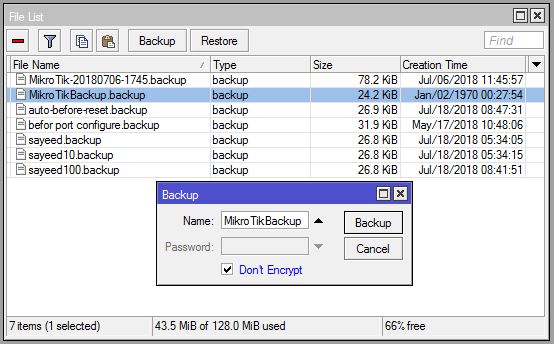
Click on Backup button. Backup window will appear.
Put your Backup file name (MikorTikBackup) in Name input field.
You can optionally put a password if you wish to keep your configuration file password protected with encryption in Password input filed.
Click on Don’t Encrypt checkbox. You may keep it uncheck if you wish to keep your configuration file encrypted but if you wish to use this backup file for password recovery, you have to check this checkbox otherwise password recovery tool cannot recover user password from an encrypted backup file.
Click on Backup button.
You will now find your backup file (MikorTikBackup.backup) in File List window.
Drag and Drop this backup file to your computer. Your backup file will be downloaded to your desired location. You can also use any FTP client (FileZilla) to download this backup file to your computer.
MikroTik Backup Configuration File
Alternatively, you can run the following command from your MikroTik command prompt to backup your MikroTik configuration file using command.
[admin@MikroTik] > system backup save name=MikroTikBackup dont-encrypt=yesSaving system configuration
Configuration backup saved
[admin@MikroTik] >
How to Restore MikroTik Configuration File
You can easily restore your MikroTik backup file using Winbox GUI or WebFig web interface. The following steps will show how to restore MikroTik configuration from backup file using Winbox GUI.
Login to your MikroTik Router using Winbox with admin privilege.
Click on Files menu item. File List window will appear.
Drag and Drop your backup file from Computer to File List window. You can also use any FTP Client (FileZilla) to upload your backup file to MikroTik File List window.
Click on Restore button. Restore window will appear.
Select your uploaded backup file from Backup File dropdown menu.
Put your file password if you provide it at the time of taking backup in Password input field.
Click on Restore button. You will find a confirmation window to restore and reboot the router. Click on Yes button.
Now your backup configuration will be restored successfully and your router will be rebooted.
Alternatively you can run the following command to restore your uploaded configuration file.
admin@MikroTik] > system backup load name=MikroTikBackuppassword:
How to backup and restore MikroTik configuration using Winbox has been discussed in this article. I hope you will now be able to backup and restore your MikroTik Router configuration successfully. However, if you face any confusion to backup and restore your MikroTik Router configuration, feel free to discuss in comment or contact with me from Contact page. I will try my best to stay with you.
MikroTik Port Forwarding or Port Mapping is a NAT application that is used to redirect a request from MikroTik IP address and port number combination to a local IP address and port number. For example, if you have a Web Server or FTP Server in your private/local area and want to access this local server from outside of your local area (from internet/public), you can apply MikroTik port forwarding or port mapping and can easily access your Web Server or FTP Server.
Port forwarding configuration in MikroTik Router is not so difficult task. In this article, I will show how to easily configure MikroTik Port Forwarding or Port Mapping using Winbox.
Network Diagram
MikroTik Port Forwarding Configuration
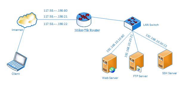
In this network, MikroTik Router’s ether1 interface is connected to WAN having IP address 117.58.—.198/29 and ether2 interface is connected to a LAN switch having IP block 192.168.10.0/24. There are three servers (Web Server, FTP Server and SSH Server) in internal network and these are only accessible from LAN. Configuring MikroTik Port Forwarding, these servers can be accessible from out of this internal network (from internet/public) and this article will show how to configure MikroTik Port Forwarding to access these internal servers from internet or public network.
MikroTik Port Forwarding Configuration
MikroTik port forwarding can be used for a lot of purposes. Among these, I will only show the following three frequently used purposes.
Port Forwarding to Internal Web Server
Port Forwarding to Internal FTP Server
Port Forwarding to Internal SSH Server
Port Forwarding to Internal Web Server
According to the network diagram, there is a Web Server (IP: 192.168.10.10) in internal network and now it is only accessible from internal network. Configuring MikroTik Port Forwarding, this Web Server can be accessible from out of this internal network and the following steps will show how to configure MikroTik Port Forwarding to access this internal Web Server from internet/public area.
Login to MikroTik Router using Winbox with admin privilege credential.
Go to IP > Firewall menu item and click on NAT tab and then click on PLUS SIGN (+). New NAT Rule window will appear.
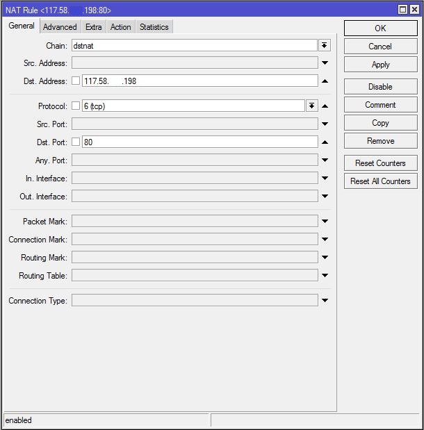
In General tab, choose dstnat from Chain dropdown menu. Put MikroTik WAN IP (117.58.—.198) in Dst. Address input field and choose tcp from Protocol dropdown menu and then put 80 in Dst Port input field because we know Web Server works on TCP port 80.
Click on Action tab and choose dst-nat option from Action dropdown menu. Put Web Server IP (192.168.10.10) in To Addresses input field and then put 80 in To Ports input field.
Click Apply and OK button.
Port Forwarding to Web Server
Port forwarding configuration to internal Web Server has been completed. Now type MikroTik WAN IP (http://117.58.—.198) in any Web browser from outside of your internal network and you will find your website in your browser successfully.
Note: You must allow HTTP service or TCP Port 80 in your Web Server firewall otherwise you cannot find your website from public network.
Port Forwarding to Internal FTP Server
In the network diagram, there is a FTP Server (IP: 192.168.10.20) and we want to access this server from public network. So, we need to configure MikroTik Port Forwarding and the following steps will show how to configure MikroTik Port Forwarding to access FTP Server from public network.
Login to MikroTik Router using Winbox with admin privilege credential.
Go to IP > Firewall menu item and click on NAT tab and then click on PLUS SIGN (+). New NAT Rule window will appear.
In General tab, choose dstnat from Chain dropdown menu. Put MikroTik WAN IP (117.58.—.198) in Dst. Address input field and choose tcp from Protocol dropdown menu and then put 21 in Dst Port input field because we know FTP Server works on TCP port 21.
Click on Action tab and choose dst-nat option from Action dropdown menu. Put FTP Server IP (192.168.10.20) in To Addresses input field and then put 21 in To Ports input field.
Click Apply and OK button.
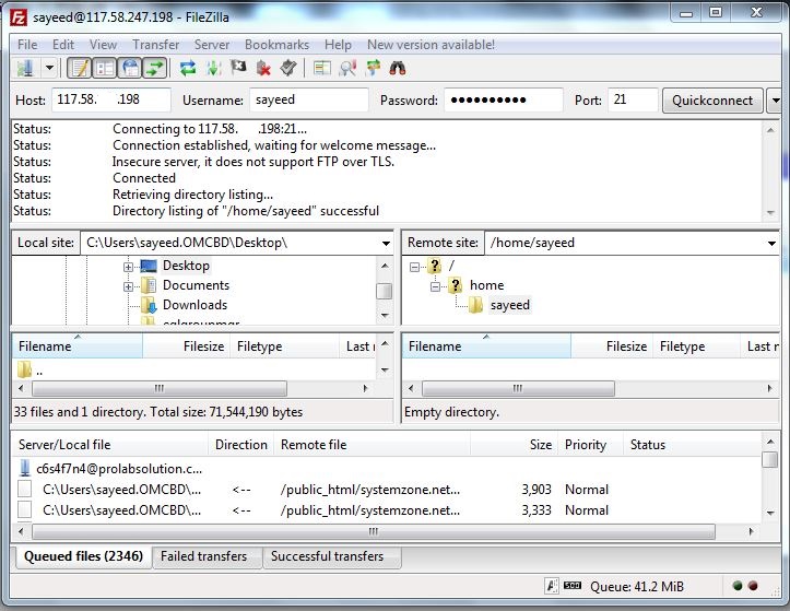
Port forwarding configuration to internal FTP Server has been completed. Now type ftp://mikrotik-wan-ip (ftp://117.58.—.198) in any web browser or use any FTP client (FileZilla) to access your FTP Server from public network. If everything is OK, you will be able to access your FTP Server successfully.
FileZilla FTP Client to Connnect FTP Server
Note: You must allow FTP service or TCP Port 21 in your FTP Server firewall otherwise you cannot communicate with your FTP Server from public network.
Port Forwarding to Internal SSH Server
We also have a SSH Server (IP: 192.168.10.30) in our network diagram and we want to access this server from outside of our internal network. MikroTik Port Forwarding configuration to access this SSH Server from public network is shown in the following steps.
Login to MikroTik Router using Winbox with admin privilege credential.
Go to IP > Firewall menu item and click on NAT tab and then click on PLUS SIGN (+). New NAT Rule window will appear.
In General tab, choose dstnat from Chain dropdown menu. Put MikroTik WAN IP (117.58.—.198) in Dst. Address input field and choose tcp from Protocol dropdown menu and then put 22 in Dst Port input field because we know SSH Server works on TCP port 22.
Click on Action tab and choose dst-nat option from Action dropdown menu. Put SSH Server IP (192.168.10.30) in To Addresses input field and then put 22 in To Ports input field.
Click Apply and OK button.
Port forwarding configuration to access internal SSH Server has been completed. Now we will be able to access our SSH Server from public network successfully by using any SSH client (Putty or SSH Secure Shell Client).
Putty SSH Client
Note: You must allow SSH service or TCP Port 22 in your SSH Server firewall otherwise you cannot communicate with your SSH Server from public network.
MikroTik Port Forwarding Configuration to Access Internal Servers has been discussed in this article. I hope you will now be able to configure your required port forwarding configuration in your MikroTik Router successfully. However, if you face any confusion, feel free to discuss in comment or contact with me from Contact page. I will try my best to stay with you.
MikroTik Router is a popular routing device to any network administrator because of having a lot of network features availability. MikroTik PPPoE Client is a special feature that is used to connect any PPPoE Server. If your ISP provides PPPoE connection, MikroTik Router is able to connect that PPPoE Server using PPPoE Client. In my previous article, I discussed how to configure MikroTik Router with static WAN connection and in this article I will show how to configure MikroTik Router with WAN PPPoE Client.
Core Devices and IP Information
To configure MikroTik Router with WAN PPPoE Client, I am using a MikroTik RouterBoard 1100 AHX2 (RouterOSv6.38.1). IP information that I am using this configuration is given below.
PPPoE username: mikrotik_wan and Password: mikrotik123
LAN Gateway: 192.168.10.1/24 and
DNS IP: 8.8.8.8 or 8.8.4.4
This information is just for my R&D purpose. Change this information according to your network requirements.
Network Diagram
To configure MikroTik Router with WAN PPPoE Client, I am following a network diagram like below image.
MikroTik WAN PPPoE Client
In this network, MikroTik Router’s ether1 interface is connected to ISP network where PPPoE Server is enabled. So, we will create MikroTik PPPoE Client in this interface so that MikroTik Router can connect with ISP PPPoE Server and can access internet. Again, MikroTik Router’s ether2 interface is connected to a LAN switch having IP block 192.168.10.0/24. We are assigning static IP for LAN users but if we want, we can configure MikroTik PPPoE Server, MikroTik DHCP Server or MikroTik Hotspot Server on ether2 interface. We will also configure NAT in our MikroTik Router so that LAN users are able to get internet using this private IP block.
MikroTik Configuration with WAN PPPoE Client
We will now start our MikroTik Router configuration with WAN PPPoE client according to the above network diagram. Complete MikroTik configuration with PPPoE WAN connection can be divided into four steps.
MikroTik PPPoE Client Configuration on WAN Interface
Assigning LAN Gateway
Assigning DNS IP and
NAT configuration
Step 1: MikroTik PPPoE Client Configuration on WAN Interface
If your uplink ISP provides PPPoE connection, you must configure MikroTik PPPoE Client on your WAN interface. The following steps will show how to configure PPPoE Client on MikroTik WAN interface.
Login to MikroTik Router using Winbox with admin privilege credential.
Click on PPP menu item. PPP window will appear. From Interface tab, click on PLUS SIGN (+) dropdown menu and then choose PPPoE Client. New Interface window will appear.
Under General tab, put your PPPoE interface name (pppoe-wan) in Name input field and then choose your WAN interface (ether1) from Interfaces dropdown menu.
Click on Dial Out tab and put your ISP given username (mikrotik_wan) in User input field and password (mikrotik123) in Password input field. Click on Dial On Demand checkbox and Use Peer DNS checkbox. Also ensure that Add Default Route checkbox is checked. Also uncheck all the checkboxes except pap checkbox from Allow panel.
Click Apply and OK button.
MikroTik PPPoE Client Configuration
MikroTik PPPoE Client will be connected now and you can see PPPoE Client status from Status tab. You will find that a dynamic IP is added in IP > Address list and you will also find a default route is automatically added in IP > Routes list by MikroTik PPPoE client.
Step 2: Assigning LAN Gateway
After MikroTik PPPoE Client configuration, we will now assign LAN Gateway IP so that LAN user can communicate with MikroTik Router. The following steps will show how to assign LAN Gateway IP in MikroTik Router.
Go to IP > Addresses menu item. Address List window will appear.
Click on PLUS SIGN (+) and put your LAN gateway IP (192.168.10.1/24) in Address input field.
Choose your LAN interface (ether2) from Interface dropdown menu.
Click Apply and OK button.
LAN Gateway IP has been assigned. Now we will assign DNS IP in our MikroTik Router.
Step 3: Assigning DNS IP
According to our PPPoE Client configuration, DNS IP will be assigned dynamically if ISP provides DNS IP with their PPPoE Server’s user profile. However, we will assign DNS Server IP manually in our MikroTik Router because they may forget to assign DNS Server IP with their user profile. The following steps will show how to assign DNS IP in your MikroTik Router.
Go to IP > DNS menu item and put DNS Server IP (8.8.8.8 or 8.8.4.4) in Servers input field.
Click on Apply and OK button.
Assigning DNS IP has been completed. Now we will configure NATing so that LAN user can get internet through MikroTik Router.
Step 4: NAT Configuration
In the last step, we will create a NAT firewall rule to masquerade our LAN IP block. Otherwise, our LAN user cannot access internet through our MikroTik router. The following steps will show how to create the masquerade firewall rule in your MikroTik router.
Go to IP > Firewallmenu and click on NAT tab and then click on PLUS SIGN (+). New NAT Rule window will appear now.
Choose srcnatfrom Chain dropdown menu and put LAN IP block (192.168.10.0/24) in Address input field.
Click on Action tab and choose masqueradefrom Action dropdown menu.
Click Applyand OK
NAT configuration in MikroTik router has been completed as well as all our necessary steps to configure MikroTik Router with WAN PPPoE Client have been completed. Now connect your LAN users to MikroTik Router through a LAN switch. If everything is OK, your LAN users will able to get internet through MikroTik Router.
MikroTik Router Configuration with WAN PPPoE Client has been discussed in this article. I hope you are now able to configure MikroTik PPPoE Client if your ISP uses PPPoE Server for their connection. However, if you face any confusion to configure MikroTik WAN PPPoE connection, feel free to discuss in comment or contact with me from Contact page. I will try my best to stay with you.
A VLAN (Virtual LAN) is a group of computers, servers, network printers and other network devices that behave as if they were connected to a single network. VLAN is a logical topology that divides a single broadcast domain into multiple broadcast domains. VLAN is a layer 2 method. So, a manageable switch is required to manage VLAN in your network and a router is required to route and control your inter-VLAN.
VLAN increases network security and performance as well as improves IT efficiency. So, it will be a better plan to implement VLAN in your network. If you have or manage MikroTik Router and manageable switch, VLAN implementation in your network is not so difficult. In this article, I will show how to easily configure inter-VLAN routing with MikroTik Router and manageable switch.
Core Devices and IP Information
To configure a VLAN network and inter-VLAN routing, I am using a MikroTik RouterBoard 1100 AHX2 (RouterOSv6.38.1) and Level One (GEP-2450) manageable switch. IP information that I am using for VLAN network configuration are given below.
WAN IP 192.168.30.2/30 and Gateway IP 192.168.30.1
LAN networks: 10.10.20.0/24, 10.10.30.0/24 and 10.10.40.0/24
DNS IP: 8.8.8.8 and 8.8.4.4
This IP information is just for my R&D purpose. Change this information according to your network requirements.
Important VLAN Terms
There are two important VLAN terms that must keep under your knowledge otherwise you may face difficulty while configuring VLAN in your manage switch.
Access Link/Port: This type of link is only part of one VLAN and it is referred to as the native VLAN of the port. Any device attached to an access link/port is unaware of a VLAN membership – the device just assumes that it is a part of a broadcast domain but it has no understanding of the physical network.
Trunk Link/Port: Trunks can carry multiple VLANs. A trunk link is a point to point link between two switches or between a switch and router. These carry the traffic of multiple VLANs (from 1 to 1005 at a time). Trunking allows you to make a single port part of multiple VLANs at the same time.
Network Diagram
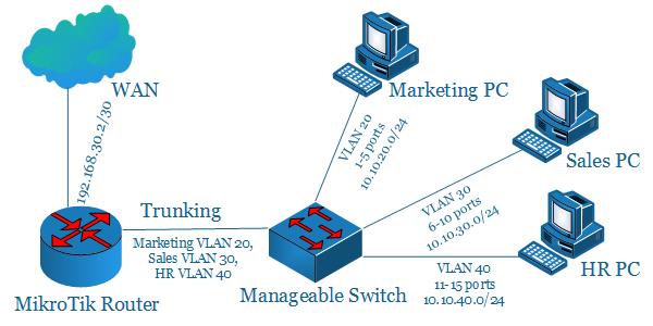
To configure a VLAN network with MikroTik Router and manageable switch, I am following a network diagram like below image.
MikroTik VLAN with Manageable Switch
In this network, MikroTik Router’s WAN (ether1) interface is connected to ISP having IP Address 192.168.30.2/30 and ether2 interface which is connected to a manageable switch is MikroTik’s LAN interface. We will create three VLAN (VLAN 20, VLAN 30 and VLAN 40) in LAN interface and its network will be 10.10.20.0/24, 10.10.30.0/24 and 10.10.40.0/24 respectively. We will configure inter-VLAN routing in our MikroTik Router and we will also configure VLAN in our manage switch (Level One GEP-2450) where 1-5 ports will keep under VLAN 20 (for Marketing Department), 6-10 ports will keep under VLAN 30 (for Sales Department), 11-15 ports will keep under VLAN 40 (for HR Department) and 16-23 ports will keep under default VLAN 1. Port 24 will be trunk port and other ports are access port.
MikroTik Inter VLAN Routing Configuration with Manageable Switch
We will now start inter-VLAN routing configuration. Complete VLAN configuration can be divided into two parts.
Inter VLAN Routing Configuration in MikroTik Router
VLAN Configuration in Manageable Switch
Part 1: Inter VLAN Routing Configuration in MikroTik Router
If multiple VLANs are implemented on a manageable switch, a router is required to provide communication between these VLANs. We know that switch is a layer 2 device. So, switch forwards only Ethernet header and cannot check IP header. For this reason, we must use a router that will work as a gateway for each VLAN. Without a router, a host is unable to communicate outside of its own VLAN. Routing process between VLANs is knows as inter-VLAN routing.
To configure inter-VLAN routing, we will create a trunk link between MikroTik Router and our manage switch that will carry traffic from three VLANs (VLAN 20 and VLAN 30 and VLAN 40). The following steps will show how to configure inter-VLAN routing as well as other basic configuration in our MikroTik Router.
Login to MikroTik Router using winbox with admin privilege credential.
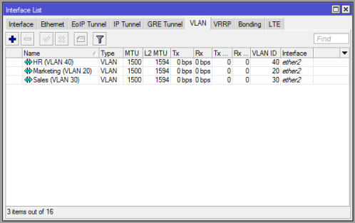
Click on Interfaces menu item. Interface List window will appear. Click on VLAN tab and then click on PLUS SIGN (+). New Interface window will appear.
Put interface name (Marketing VLAN 20) in Name input box and put VLAN ID (20) in VLAN ID input box and choose your physical interface (ether2) that will be used as trunk link from Interface dropdown menu and then click on Apply and OK button. Similarly, create VLAN 30 (Sales VLAN 30) and VLAN 40 (HR VLAN 40) interfaces. Your VLAN interface list window looks like below image.
Go to IP > Addresses menu item and click on PLUS SIGN (+). In New Address window, put WAN IP address (192.168.30.2/30) in Address input field and choose WAN interface (ether1) from Interface dropdown menu and then click on Apply and OK button.
Click on PLUS SIGN (+) again and put VLAN 20 network’s gateway IP (10.10.20.1/24) in Address input box and choose VLAN 20 interface (Marketing VLAN 20) from Interface dropdown menu and then click on Apply and OK button. Similarly, put VLAN 30 gateway IP (10.10.30.1/24) on Sales VLAN 30 interface and VLAN 40 gateway IP (10.10.40.1/24) on HR VLAN 40 interface.
Go to IP > DNS and put DNS Server IP (8.8.8.8 or 8.8.4.4) in Servers input field and click on Apply and OK button.
Go to IP > Firewall and click on NAT tab and then click on PLUS SIGN (+). Under General tab, choose srcnatfrom Chain dropdown menu and click on Action tab and then choose masquerade from Action dropdown menu. Click on Apply and OK button.
Go to IP > Routes and click on PLUS SIGN (+). In New Route window, click on Gateway input field and put WAN Gateway address (192.168.30.1) in Gateway input field and click on Apply and OK button.
VLAN Interface List
Inter VLAN routing and other basic configuration in MikroTik Router has been completed. Now MikroTik Router is ready to route VLAN 20, VLAN 30 and VLAN 40. In the next part, we will configure VLAN in our Level One manageable switch.
Part 2: VLAN Configuration in Manageable Switch
In this part, we will create our three VLANs (VLAN 20, VLAN 30 and VLAN 40) and configure access port and trunk port in our manage switch. Any manageable switch can be used for this purpose. As I have Level One (GEP-2450) switch available, I am doing VLAN configuration in this manage switch. If you have other manageable switch, find the manual in Google about how to configure VLAN in that specific manage switch.
Level One (GEP-2450) switch is a web smart manageable switch. So, we can manage this switch using web GUI. GEP-2450 switch has 24 Ethernet port. Among them, we will use 1-5 ports as VLAN 20 access port for Marketing Department, 6-10 ports as VLAN 30 access port for Sales Department, 11-15 ports as VLAN 40 access port for HR Department and 16-23 ports will keep under default VLAN 1. Port 24 will be used as trunk port and all other ports will be used as access port. The following steps will show you how to configure VLAN in Level One (GEP-2450) switch properly.
Connect port 24 with your MikroTik Router’s ether2 port with a RJ45 cable. This link will be used as trunk link.
Connect your PC and switch with a RJ45 cable. Use switch port one of 16-23 ports for this connection.
Default IP address of Level One (GEP-2450) switch is 192.168.1.1/24. So, assign an IP address of this block in your PC and then type https://192.168.1.1 in your favorite web browser. Now it will ask to provide password. Default password for Level One (GEP-2450) switch is So, put this password and hit enter. Now you will find configuration GUI for the switch.
Go to VLANs > VLAN Mode and ensure VLAN Mode is Tag-based.
Go to VLANs > VLAN Group. Tag-Based VLAN Configuration page will appear.
Put VLAN ID (20) in VLAN ID input box and click on Add button. VLAN Setup page will appear. Select port 1-5 and port 24 and then click on Apply button. Similarly, create VLAN 30 and VLAN 40 and select port 6-10 and port 11-15 respectively and port 24 for both VLAN. You will find your created VLAN in VLAN Configuration List area.
Select VLAN ID 1 and click on Modify button. VLAN Setup page for VLAN 1 will appear. Unselect port 1-15 and click on Apply button.
Now click on Port Config button under VLAN Port Configuration area. VLAN Per Port Configuration page will appear. Change PVID 0 to 20 from 1-5 ports, 0 to 30 from 6-10 ports and 0 to 40 from 11-15 ports. All ports Role will be Access except port 24. Choose Trunk role for port 24 from Role dropdown menu. Click on Apply button.
VLAN configuration in Level One (GEP-2450) switch has been completed. VLAN Group page now looks like below image.
VLAN Configuration in Level One (GEP-2450) Switch
Now connect your Marketing PC to 1-5 ports, Sales PC to 6-10 ports and HR PC to 11-15 ports. If everything is OK, your desired PC will be able to get internet connection through your manage switch and MikroTik Router.
Block Inter VLAN Communication
Sometimes it may be your requirements to block inter VLAN communication. For example, you may want that your Marketing Department cannot communicate with Sales Department. In this case, you have to apply firewall rule to block inter VLAN communication because by default MikroTik allow inter VLAN communication. The following steps will show how to create firewall rule to block inter-VLAN communication.
Login to MikroTik Router and go to IP > Firewall menu item and click on Filter Rules tab and click on PLUS SIGN (+). New Firewall Rule window will appear.
Choose forward from Chain dropdown menu.
Put Marketing Department’s IP block (10.10.20.0/24) in Src. Address input box and Sales Department’s IP block (10.10.30.0/24) in Dst. Address input box.
Choose tcp from Protocol dropdown menu.
Click on Action tab and choose drop from Action dropdown menu.
Click on Apply and OK button.
This firewall rule blocks all TCP connections coming from Marketing PC to Sales PC. Similarly, you can block all TCP connections or UDP connections coming from Sales PC to Marketing PC by creating another firewall rule and changing source address block, destination address block and protocol.
MikroTik inter-VLAN routing configuration with manageable switch has been discussed in this article. I hope, you will be able to create VLAN in your network with MikroTik Router and manageable switch. However, if you face any confusion while configuring VLAN, feel free to discuss in comment or contact with me from Contact page. I will try my best to stay with you.
Hi geek, you are here because you are finding a complete MikroTik Dual WAN PCC Load balancing and Link Redundancy solution with PPPoE Server because you have managed two ISP connections and want to provide an uninterrupted internet connection to your clients. You also want to manage your LAN clients with PPPoE Server because it provides a hassle free network administration.
MikroTik PCC provides 100% reliable Load Balancing and Link Redundancy network and in my previous article I discussed how MikroTik PCC work and how to configure a basic MikroTik PCC Load Balancing and Link Redundancy network. In this article I will show how to configure a complete Dual WAN PCC Load Balancing and Link Redundancy network with MikroTik PPPoE Server.
Core Devices and IP Information
To configure a PCC load balancing and link redundancy network with PPPoE Server, I am using MikroTik RouterOSv6.38.1 which has two ISP connections available. IP information that I am using for this network configuration are given below.
ISP1 IP 192.168.30.2/30 and Gateway IP 192.168.30.1
ISP2 IP 192.168.60.2/30 and Gateway IP 192.168.60.1
LAN network: 10.10.70.0/24 and LAN Gateway IP 10.10.70.1/24
DNS IP: 8.8.8.8 and 8.8.4.4
This IP information is just for my RND purpose. Change this information according to your network requirements.
Network Diagram
To configure a Load Balancing and Link Redundancy network with MikroTik RouterOS, I am following a network diagram like below image.
MikroTik PCC Load Balancing with PPPoE Server Network
In this network, MikroTik Router’s 1st Interface (ether1) is connected to ISP1 having IP Address 192.168.30.2/30 and 2nd Interface (ether2) is connected to ISP2 having IP Address 192.168.60.2/30. In real network these IP Addresses should replace with your ISP given public IP Address. Again, 3rd Interface (ether3) is our LAN interface where PPPoE server will be installed and PPPoE network will be 10.10.70.0/24.
We will configure Dual WAN PCC Load Balancing and Link Redundancy in this MikroTik Router and after PCC configuration MikroTik will pass LAN traffic through both ISP equally and if any ISP is disconnected, other ISP will be used to pass all traffic until the disconnected ISP becomes alive. If disconnected ISP becomes alive, both ISP will be used to pass LAN traffic again automatically.
MikroTik PCC Load Balancing Configuration with PPPoE Server
We will now configure PCC Load Balancing network with PPPoE Server according to our above network diagram. Complete configuration can be divided into two parts.
MikroTik PCC load balancing configuration over DUAL WAN
PPPoE server configuration for LAN
Part 1: MikroTik PCC Load Balancing Configuration over DUAL WAN
In first part, we will do PCC Load Balancing and Link Redundancy configuration. Complete PCC load balancing configuration includes assigning WAN IP, creating mangle rule, policy based routing configuration and NAT configuration. We will now perform these tasks in our MikroTik Router.
Assigning WAN IP
We have two WAN IPs given from ISP1 and ISP2. We will now assign this WAN IPs in our MikroTik Router’s WAN interface. The following steps will show how to assign WAN IP in your MikroTik Router.
Login to MikroTik Router with winbox (with admin privilege credential).
Click on Interfaces menu item. Interface List window will appear.
Double click on ether1 interface and rename it as ISP1 and then click Apply and OK button. Similarly, click on ether2 interface and rename it as ISP2 and then click Apply and OK button. Again, click on ether3 interface and rename it as LAN and then click Apply and OK button.
Go to IP > Addresses menu item and click on PLUS SIGN (+). In New Address window, put ISP1 IP address (192.168.30.2/30) in Address input field and choose ISP1 from Interface dropdown menu and then click on Apply and OK button.
Similarly, click on PLUS SIGN (+). In New Address window, put ISP2 IP address (192.168.60.2/30) in Address input field and choose ISP2 from Interface dropdown menu and then click on Apply and OK button.
Alternatively, you can run below command from MikroTik CLI.
/interfaceset “ether1″ name=”ISP1”
set “ether2″ name=”ISP2”
set “ether3″ name=”LAN”
/ ip address
add address=192.168.30.2/30 interface=ISP1
add address=192.168.60.2/30 interface=ISP2
Assigning WAN IP in MikroTik Router has been completed. Now we will create Mangle rule to mark connection and routing.
Creating Mangle Rule
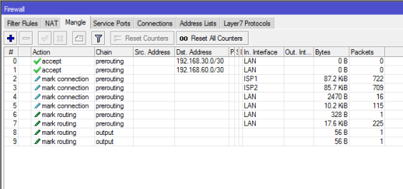
Mangle rule is used to mark packet for proper routing. In this part we will create various mangle rules that will help to mark connection and routing and pass different network traffics to different WAN connections. Go to IP > Firewall menu item and click on Mangle tab and create the following 10 rules as indicated.
Click on PLUS SIGN (+). New Mangle Rule window will appear. Click on General tab and choose prerouting from Chain dropdown menu and put ISP1 network address (192.168.30.0/30) in Dst. Address input and then choose LAN from In. Interface dropdown menu. Now click on Action tab and choose accept from Action dropdown menu and then click on Apply and OK button.
Click on PLUS SIGN (+). New Mangle Rule window will appear. Click on General tab and choose prerouting from Chain dropdown menu and put ISP2 network address (192.168.60.0/30) in Dst. Address input and then choose LAN from In. Interface dropdown menu. Now click on Action tab and choose accept from Action dropdown menu and then click on Apply and OK button.
Click on PLUS SIGN (+). New Mangle Rule window will appear. Click on General tab and choose prerouting from Chain dropdown menu and choose ISP1 from In. Interface dropdown menu and then choose no-mark from Connection Mark dropdown menu. Now click on Action tab and choose mark connection from Action dropdown menu and put a connection mark name (ISP1_conn) in New Connection Mark input field. Uncheck Passthrough checkbox if it is checked. Click on Apply and OK button.
Click on PLUS SIGN (+). New Mangle Rule window will appear. Click on General tab and choose prerouting from Chain dropdown menu and choose ISP2 from In. Interface dropdown menu and then choose no-mark from Connection Mark dropdown menu. Now click on Action tab and choose mark connection from Action dropdown menu and put a connection mark name (ISP2_conn) in New Connection Mark input field. Uncheck Passthrough checkbox if it is checked. Click on Apply and OK button.
Click on PLUS SIGN (+). New Mangle Rule window will appear. Click on General tab and choose prerouting from Chain dropdown menu and choose LAN from In. Interface dropdown menu and then choose no-mark from Connection Mark dropdown menu. Click on Advanced tab and choose both addresses from Per Connection Classifier dropdown menu and put 2 in next 1st input field and 0 in 2nd input field. Click on Extra tab and click on Dst. Address Type option and choose local from Address Type dropdown menu and then click on Invert checkbox. Click on Action tab and choose mark connection from Action dropdown menu and put a connection mark name (ISP1_conn) in New Connection Mark input field. Uncheck Passthrough checkbox if it is checked. Click on Apply and OK button.
Click on PLUS SIGN (+). New Mangle Rule window will appear. Click on General tab and choose prerouting from Chain dropdown menu and choose LAN from In. Interface dropdown menu and then choose no-mark from Connection Mark dropdown menu. Click on Advanced tab and choose both addresses from Per Connection Classifier dropdown menu and put 2 in next 1st input field and 1 in 2nd input field. Click on Extra tab and click on Dst. Address Type option and choose local from Address Type dropdown menu and then click on Invert checkbox. Click on Action tab and choose mark connection from Action dropdown menu and put a connection mark name (ISP2_conn) in New Connection Mark input field. Uncheck Passthrough checkbox if it is checked. Click on Apply and OK button.
Click on PLUS SIGN (+). New Mangle Rule window will appear. Click on General tab and choose prerouting from Chain dropdown menu and choose LAN from In. Interface dropdown menu and then choose ISP1_conn from Connection Mark dropdown menu. Now click on Action tab and choose mark routing from Action dropdown menu and put a routing mark name (to_ISP1) in New Routing Mark input field. Uncheck Passthrough checkbox if it is checked. Click on Apply and OK button.
Click on PLUS SIGN (+). New Mangle Rule window will appear. Click on General tab and choose prerouting from Chain dropdown menu and choose LAN from In. Interface dropdown menu and then choose ISP2_conn from Connection Mark dropdown menu. Now click on Action tab and choose mark routing from Action dropdown menu and put a routing mark name (to_ISP2) in New Routing Mark input field. Uncheck Passthrough checkbox if it is checked. Click on Apply and OK button.
Click on PLUS SIGN (+). New Mangle Rule window will appear. Click on General tab and choose output from Chain dropdown menu and then choose ISP1_conn from Connection Mark dropdown menu. Now click on Action tab and choose mark routing from Action dropdown menu and put a routing mark name (to_ISP1) in New Routing Mark input field. Uncheck Passthrough checkbox if it is checked. Click on Apply and OK button.
Click on PLUS SIGN (+). New Mangle Rule window will appear. Click on General tab and choose output from Chain dropdown menu and then choose ISP2_conn from Connection Mark dropdown menu. Now click on Action tab and choose mark routing from Action dropdown menu and put a routing mark name (to_ISP2) in New Routing Mark input field. Uncheck Passthrough checkbox if it is checked. Click on Apply and OK button.
Alternatively, you can run below command from MikroTik CLI.
/ ip firewall mangleadd chain=prerouting dst-address=192.168.30.0/30 action=accept in-interface=LAN
Mangle rules for matching and marking packets has been created successfully. Now we will configure policy based routing so that marked packet can be routed properly through appropriate ISP connection.
Policy Based Routing Configuration
Mangle rules that we have created will mark connection but do not do anything in routing. To pass marked connection to appropriate ISP connection, we need to configure policy based routing. The following steps will show how to configure policy based routing for the marked connection.
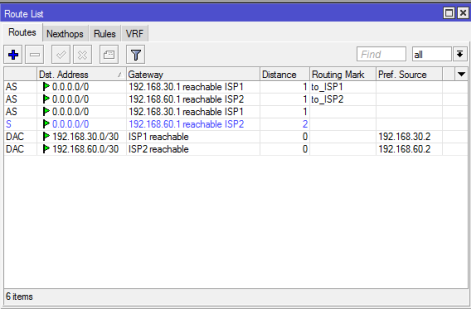
Go to IP > Routes menu item. Route List window will appear.
Click on PLUS SIGN (+). New Route window will appear. Put ISP1 gateway address (192.168.30.1) in Gateway input field. Choose ping from Check Gateway dropdown menu. Choose ISP1 routing mark (to_ISP1) from Routing Mark dropdown menu. Click Apply and OK button.
Click on PLUS SIGN (+). New Route window will appear. Put ISP2 gateway address (192.168.60.1) in Gateway input field. Choose ping from Check Gateway dropdown menu. Choose ISP2 routing mark (to_ISP2) from Routing Mark dropdown menu. Click Apply and OK button.
Click on PLUS SIGN (+). New Route window will appear. Put ISP1 gateway address (192.168.30.1) in Gateway input field. Choose ping from Check Gateway dropdown menu. Put 1 in Distance input field and Click Apply and OK button.
Click on PLUS SIGN (+). New Route window will appear. Put ISP2 gateway address (192.168.60.1) in Gateway input field. Choose ping from Check Gateway dropdown menu. Put 2 in Distance input field and Click Apply and OK button.
Alternatively, you can run below command from MikroTik CLI.
/ ip routeadd dst-address=0.0.0.0/0 gateway=192.168.30.1 routing-mark=to_ISP1 check-gateway=ping
Routing configuration for selecting proper ISP has been completed. Now we need to configure NATing so that LAN traffic can reach to internet.
NAT Configuration
We will now configure NATing so that LAN user can reach to internet through MikroTik Router. The following steps will guide how to configure NAT in MikroTik Router for a specific ISP connection.
Go to IP > Firewall menu item and click on NAT tab.
Click on PLUS SIGN (+). New NAT Rule window will appear. In General tab, choose srcnat from Chain dropdown menu and choose ISP1 from Out. Interface dropdown menu. Click on Action tab and choose masquerade from Action dropdown menu and click Apply and OK button.
Similarly, click on PLUS SIGN (+) again. New NAT Rule window will appear. In General tab, choose srcnat from Chain dropdown menu and choose ISP2 from Out. Interface dropdown menu. Click on Action tab and choose masquerade from Action dropdown menu and click Apply and OK button.
Alternatively, you can run below command from MikroTik CLI.
/ ip firewall natadd chain=srcnat out-interface=ISP1 action=masquerade
NAT configuration as well as PCC Load Balancing and Link Redundancy configuration has been completed. Now we will configure PPPoE server in MikroTik Router to manage our LAN users easily.
Part 2: PPPoE Server Configuration for LAN
PPPoE provides extensive user management and network management benefits to network administrators. So it is always better to use PPPoE server for managing LAN user. Complete PPPoE Server configuration can be divided into the following four steps.
IP Pool Configuration
Enabling PPPoE Server
User Profile Configuration and
User Secrets (username and password) Configuration
IP Pool Configuration
IP Pool is IP range from where IP will be assigned to user computer after user authentication. The following steps will show how to create IP Pool in your MikroTik Router.
Go to IP > Poolmenu item and click on PLUS SIGN (+). New IP Pool window will appear now. Put a pool name (LAN_Pool) in Name input field and address range (172.16.0.2-172.16.0.254) in Addresses input field.
Click Applyand OK
You can create as many IP Pools as you want following the above steps properly.
IP Pool configuration has been completed. Now we will enable PPPoE Server in MikroTik Router.
Enabling PPPoE Server
We will now enable PPPoE Server in our MikroTik Router. The following steps will show how to enable PPPoE Server in MikroTik Router.
Click on PPPmenu item and click on PPPoE Servers tab and then click on PLUS SIGN (+). New PPPoE Service window will appear now. Put your PPPoE Server name (LAN_PPPoE_Server) in Service Name input box.
Now choose your LAN interface (LAN) where PPPoE Server will be enabled from Interfacedrop-down menu.
Click on One Session Per Hostif you don’t want to allow multiple session from one computer.
At the bottom of this window, you can see four authentication methods. Select only PAP, and unselect all other options. Now click Applyand OK button.
PPPoE Server configuration in MikroTik router has been completed. Now we will create user profile so that we can apply user limitation and other user settings easily.
User Profile Configuration
User profile gives benefits to apply user settings and user limitation such as user bandwidth and number of user connection limitation. User profile also gives facility to categorize your LAN users. The following steps will show how to create user profile for your PPPoE users.
Click on Profiles tab. You will see two default profiles are already created by MikroTik RouterOS. We will do nothing with the default profiles. Rather we will create a new profile. Click on PLUS SIGN (+). New PPP Profile window will appear now.
Put your profile name (LAN_User_Profile) in Name input field. Now put LAN Gateway (10.10.70.1) in Local Address input field and choose your IP Pool (LAN_Pool) from Remote Address drop-down menu. Note that Local Address is the gateway address of this IP block which not included in LAN_Pool. So, when a user will be connected to this profile, he/she will get an IP from LAN_Pool and his/her gateway will be 10.10.70.1.
At the bottom of this window, put your DNS server IP that you have got from your ISP or put Google’s public DNS 8.8.8.8 in DNS Server input box.
Optionally, you can set bandwidth limit and number of connection limit for this profile user from Limits To set bandwidth limit, click on Limits tab and put download and upload speed in Rate Limit (rx/tx)input box in bit. For example, type 512000/512000 for this profile if you want all users of this profile get 512kbps upload and download speed. Also click on yes radio button from Only One panel. If you keep it default or no, multiple computers can be connected with same username and password. Obviously, you don’t want it.
Now click Apply and OK button.
You can create as many user profiles as you want following the above steps properly.
User profile configuration has been completed. Now we will create user secret (username and password) so that they can connect to our PPPoE server with this secret.
User Secret Configuration
Now we will create user secret that will be used to connect to PPPoE Server. The following steps will show how to create user secret in your MikroTik Router.
From PPP window, click on Secretstab and then click on PLUS SIGN (+). New PPP Secret window will appear now.
Put client username in the Nameinput box and password in Password input box. Note that username and password is necessary when any client will be connected from his workstation (PC, Laptop, Router and so on). Also, it is case-sensitive. So, be careful to put these fields.
Now choose pppoefrom Service drop-down list and choose profile for this user (LAN_User_Profile) from Profile drop-down list.
Optionally, you can bind any device with this username and password providing MAC address. Put MAC address of any device in Caller IDinput box. If you put MAC address of any device in Caller ID, only this device can be connected with this secret (username and password).
You can create as many secrets as you want following the above steps.
User secret configuration has been completed as well as all the steps for configuring a PPPoE service in MikroTik router has been completed. Now it is time to show how to configure PPPoE client in any operating system.
PPPoE Client Configuration
We have completely configured PPPoE Server in MikroTik Router. Now your MikroTik is ready to accept PPPoE client. A number of PPPoE clients are present now a day. Among them, now I will show how to configure PPPoE client in windows 7 operating system. All other versions of windows operating system follow almost the same procedure. So, you don’t face any difficulty, I think. However, if you feel any problem to configure PPPoE client of any operating platform, I recommend you to go Google and search how to configure PPPoE client of that specific operating platform.
Steps to Create PPPoE dial Up Connection in Windows 7
Microsoft PC dialer is used to connect remote PPPoE Server in window 7 to get access to the internet. So, you have to configure Microsoft PC dialer in windows 7 PC to get access to the internet through your MikroTik Router. Follow my bellow steps to create PPPoE connection in windows 7 with built in PPPoE wizard.
Connect an Ethernet cable to windows 7 PC from your network switch.
Open Network and Sharing Centerfrom Control Panel.
Now click on Setup a new connection or networklink under Change your networking settings area.Set Up a Connection or Network window will appear.
In this window, click on Connect to the internetoption and click the Next Connect to the Internet window will appear.
Click on Broadband (PPPoE)option from this window and put username and password that you have created in PPP secret configuration step in User name and Password input field accordingly. Optionally, you can change connection name in Connection name input field and you can also click on Remember this password option otherwise you have to provide password every time you start your PC. Now click on Connect If you provide correct username and password, The connection to the Internet is ready to use message will be shown. Now click on Close A dialer will be created in your windows 7 PC and you can enter your credential anytime to connect Internet with this dialer.
You are now connected to the internet with PPPoE dialer. Browse any site. I hope, you will be successful to browse any site now.
MikroTik Dual WAN Load Balancing with PPPoE Server has been discussed in this article. I hope you are now able to configure your Load Balancing network with PPPoE Server in MikroTik Router. However, if you face any confusion, feel free to discuss in comment or contact with me from Contact page. I will try my best to stay with you.