На всех роутерах в mikrotik сохранить конфигурацию очень просто, если у вас установлена утилита winbox для конфигурирования RouterOS то лучше всего воспользоваться ей. Открываем ее идем в раздел Files – Backup, далее задаем имя и нажимаем на кнопку «backup». Читать →
Не для кого не секрет что пароль по умолчанию mikrotik отсутствует и при подключении к новой железке вводим только логин admin а поле пароль оставляем пустым. И это касается абсолютно всех их устройств будь то hab lite или какой-то hab ac2, ну вы поняли. Еще раз повторю стандартный пароль mikrotik – отсутствует (его нет). Читать →
Hi, you are here means you are finding a Load Balancing and Link Redundancy solution with Unequal WAN links in your MikroTik Router. If so, it is your right place. In my previous article I discussed how to configure a Dual WAN Load Balancing and Link Redundancy network using PCC method but it was assumed that both WAN links have equal bandwidth. But in real situation, you may have unequal WAN links such as ISP1 may have 10MB bandwidth and ISP2 may have 20MB bandwidth. In this case, PCC Load Balancing and Link Redundancy configuration will be a little bit different. So, in this article I will show how to configure Load Balancing and Link Redundancy network using PCC method which will have unequal Dual WAN connections.
Core Devices and IP Information
To configure a load balancing with failover network, I am using MikroTik RouterOSv6.38.1 that has two ISP connections and a LAN network. IP information that I am using for this network configuration are given below.
ISP1 IP 192.168.30.2/30 and Gateway IP 192.168.30.1
ISP2 IP 192.168.60.2/30 and Gateway IP 192.168.60.1
LAN network: 10.10.70.0/24 and LAN Gateway IP 10.10.70.1/24
DNS IP: 8.8.8.8 and 8.8.4.4
This IP information is just for my RND purpose. Change this information according to your network requirements.
Network Diagram
To configure a Load Balancing and Link Redundancy network with MikroTik RouterOS, I am following a network diagram like below image.
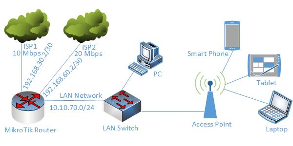
MikroTik PCC Load Balancing over Unequal WAN
In this network, MikroTik Router’s 1st Interface (ether1) is connected to ISP1 having IP Address 192.168.30.2/30 and 10 Mbps bandwidth and 2nd Interface (ether2) is connected to ISP2 having IP Address 192.168.60.2/30 and 20 Mbps bandwidth. In real network these IP Addresses should replace with your ISP given public IP Address. Again, 3rd Interface (ether3) is connected to LAN having IP network 10.10.70.0/24.
We will configure Dual WAN Load Balancing and Link Redundancy in this MikroTik Router using PCC method and after PCC configuration MikroTik will pass one third LAN traffic through ISP1 connection and two third LAN traffic through ISP2 connection and if any ISP is disconnected, other ISP will be used to pass all LAN traffic until the disconnected ISP becomes alive. If disconnected ISP becomes alive, both ISP will be used to pass LAN traffic again automatically.
MikroTik Load Balancing with Failover Configuration over Unequal WAN Links
We will now configure PCC Load Balancing with failover according to our above network diagram. Complete configuration can be divided into the following four parts.
MikroTik Router basic configuration
Creating Mangle rule
Policy based routing configuration
NAT configuration
Part 1: MikroTik Router Basic Configuration
In the basic part, we will assign 1st WAN IP address given from ISP1, 2nd WAN IP address given from ISP2, LAN gateway and DNS. The following steps will show how to perform these steps in MikroTik Router.
Login to MikroTik Router with winbox by admin privilege credential.
Click on Interfaces menu item. Interface List window will appear.
Double click on ether1 interface and rename it as ISP1 and then click Apply and OK button. Similarly, click on ether2 interface and rename it as ISP2 and then click Apply and OK button. Again, click on ether3 interface and rename it as LAN and then click Apply and OK button.
Go to IP > Addresses menu item and click on PLUS SIGN (+). In New Address window, put ISP1 IP address (192.168.30.2/30) in Address input field and choose ISP1 from Interface dropdown menu and then click on Apply and OK button.
Similarly, click on PLUS SIGN (+). In New Address window, put ISP2 IP address (192.168.60.2/30) in Address input field and choose ISP2 from Interface dropdown menu and then click on Apply and OK button.
Again, click on PLUS SIGN (+). In New Address window, put LAN Gateway IP address (10.10.70.1/24) in Address input field and choose LAN from Interface dropdown menu and then click on Apply and OK button.
Go to IP > DNS menu item and put DNS IP (8.8.8.8) in Servers input field and click Apply and OK button.
Alternatively, you can run below command from MikroTik CLI.
/interfaceset “ether1″ name=”ISP1”
set “ether2″ name=”ISP2”
set “ether3″ name=”LAN”
/ ip address
add address=192.168.30.2/30 interface=ISP1
add address=192.168.60.2/30 interface=ISP2
add address=10.10.70.1/24 interface=LAN
MikroTik Router basic configuration has been completed. Now we will create Mangle rule to mark connection and routing.
Part 2: Creating Mangle Rule
Mangle rule is used to mark packet for proper routing. In this part we will create various mangle rules that will help to mark connection and routing and pass different network traffics to different WAN connections. Go to IP > Firewall menu item and click on Mangle tab and create the following 10 rules as indicated.
Click on PLUS SIGN (+). New Mangle Rule window will appear. Click on General tab and choose prerouting from Chain dropdown menu and put ISP1 network address (192.168.30.0/30) in Dst. Address input and then choose LAN from In. Interface dropdown menu. Now click on Action tab and choose accept from Action dropdown menu and then click on Apply and OK button.
Click on PLUS SIGN (+). New Mangle Rule window will appear. Click on General tab and choose prerouting from Chain dropdown menu and put ISP2 network address (192.168.60.0/30) in Dst. Address input and then choose LAN from In. Interface dropdown menu. Now click on Action tab and choose accept from Action dropdown menu and then click on Apply and OK button.
Click on PLUS SIGN (+). New Mangle Rule window will appear. Click on General tab and choose prerouting from Chain dropdown menu and choose ISP1 from In. Interface dropdown menu and then choose no-mark from Connection Mark dropdown menu. Now click on Action tab and choose mark connection from Action dropdown menu and put a connection mark name (ISP1_conn) in New Connection Mark input field. Uncheck Passthrough checkbox if it is checked. Click on Apply and OK button.
Click on PLUS SIGN (+). New Mangle Rule window will appear. Click on General tab and choose prerouting from Chain dropdown menu and choose ISP2 from In. Interface dropdown menu and then choose no-mark from Connection Mark dropdown menu. Now click on Action tab and choose mark connection from Action dropdown menu and put a connection mark name (ISP2_conn) in New Connection Mark input field. Uncheck Passthrough checkbox if it is checked. Click on Apply and OK button.
Click on PLUS SIGN (+). New Mangle Rule window will appear. Click on General tab and choose prerouting from Chain dropdown menu and choose LAN from In. Interface dropdown menu and then choose no-mark from Connection Mark dropdown menu. Click on Advanced tab and choose both addresses from Per Connection Classifier dropdown menu and put 2 in next 1st input field and 0 in 2nd input field. Click on Extra tab and click on Dst. Address Type option and choose local from Address Type dropdown menu and then click on Invert checkbox. Click on Action tab and choose mark connection from Action dropdown menu and put a connection mark name (ISP1_conn) in New Connection Mark input field. Uncheck Passthrough checkbox if it is checked. Click on Apply and OK button.
Click on PLUS SIGN (+). New Mangle Rule window will appear. Click on General tab and choose prerouting from Chain dropdown menu and choose LAN from In. Interface dropdown menu and then choose no-mark from Connection Mark dropdown menu. Click on Advanced tab and choose both addresses from Per Connection Classifier dropdown menu and put 2 in next 1st input field and 1 in 2nd input field. Click on Extra tab and click on Dst. Address Type option and choose local from Address Type dropdown menu and then click on Invert checkbox. Click on Action tab and choose mark connection from Action dropdown menu and put a connection mark name (ISP2_conn) in New Connection Mark input field. Uncheck Passthrough checkbox if it is checked. Click on Apply and OK button.
Click on PLUS SIGN (+). New Mangle Rule window will appear. Click on General tab and choose prerouting from Chain dropdown menu and choose LAN from In. Interface dropdown menu and then choose no-mark from Connection Mark dropdown menu. Click on Advanced tab and choose both addresses from Per Connection Classifier dropdown menu and put 2 in next 1st input field and 2 in 2nd input field. Click on Extra tab and click on Dst. Address Type option and choose local from Address Type dropdown menu and then click on Invert checkbox. Click on Action tab and choose mark connection from Action dropdown menu and put a connection mark name (ISP2_conn) in New Connection Mark input field. Uncheck Passthrough checkbox if it is checked. Click on Apply and OK button.
Click on PLUS SIGN (+). New Mangle Rule window will appear. Click on General tab and choose prerouting from Chain dropdown menu and choose LAN from In. Interface dropdown menu and then choose ISP1_conn from Connection Mark dropdown menu. Now click on Action tab and choose mark routing from Action dropdown menu and put a routing mark name (to_ISP1) in New Routing Mark input field. Uncheck Passthrough checkbox if it is checked. Click on Apply and OK button.
Click on PLUS SIGN (+). New Mangle Rule window will appear. Click on General tab and choose prerouting from Chain dropdown menu and choose LAN from In. Interface dropdown menu and then choose ISP2_conn from Connection Mark dropdown menu. Now click on Action tab and choose mark routing from Action dropdown menu and put a routing mark name (to_ISP2) in New Routing Mark input field. Uncheck Passthrough checkbox if it is checked. Click on Apply and OK button.
Click on PLUS SIGN (+). New Mangle Rule window will appear. Click on General tab and choose output from Chain dropdown menu and then choose ISP1_conn from Connection Mark dropdown menu. Now click on Action tab and choose mark routing from Action dropdown menu and put a routing mark name (to_ISP1) in New Routing Mark input field. Uncheck Passthrough checkbox if it is checked. Click on Apply and OK button.
Click on PLUS SIGN (+). New Mangle Rule window will appear. Click on General tab and choose output from Chain dropdown menu and then choose ISP2_conn from Connection Mark dropdown menu. Now click on Action tab and choose mark routing from Action dropdown menu and put a routing mark name (to_ISP2) in New Routing Mark input field. Uncheck Passthrough checkbox if it is checked. Click on Apply and OK button.
Alternatively, you can run below command from MikroTik CLI.
/ ip firewall mangleadd chain=prerouting dst-address=192.168.30.0/30 action=accept in-interface=LAN
Mangle rules for matching and marking packets has been created successfully. Now we will configure policy based routing so that marked packet can be routed properly through appropriate ISP connection.
Part 3: Policy Based Routing Configuration
Mangle rules that we have created will mark connection but do not do anything in routing. To pass marked connection to appropriate ISP connection, we need to configure policy based routing. The following steps will show how to configure policy based routing for the marked connection.
Go to IP > Routes menu item. Route List window will appear.
Click on PLUS SIGN (+). New Route window will appear. Put ISP1 gateway address (192.168.30.1) in Gateway input field. Choose ping from Check Gateway dropdown menu. Choose ISP1 routing mark (to_ISP1) from Routing Mark dropdown menu. Click Apply and OK button.
Click on PLUS SIGN (+). New Route window will appear. Put ISP2 gateway address (192.168.60.1) in Gateway input field. Choose ping from Check Gateway dropdown menu. Choose ISP2 routing mark (to_ISP2) from Routing Mark dropdown menu. Click Apply and OK button.
Click on PLUS SIGN (+). New Route window will appear. Put ISP1 gateway address (192.168.30.1) in Gateway input field. Choose ping from Check Gateway dropdown menu. Put 1 in Distance input field and Click Apply and OK button.
Click on PLUS SIGN (+). New Route window will appear. Put ISP2 gateway address (192.168.60.1) in Gateway input field. Choose ping from Check Gateway dropdown menu. Put 2 in Distance input field and Click Apply and OK button.
Alternatively, you can run below command from MikroTik CLI.
/ ip routeadd dst-address=0.0.0.0/0 gateway=192.168.30.1 routing-mark=to_ISP1 check-gateway=ping
Routing configuration for selecting proper ISP has been completed. Now we need to configure NATing so that LAN traffic can reach to internet.
Part 4: NAT Configuration
In last part, we will configure NATing. Otherwise LAN user cannot reach to internet through MikroTik Router. The following steps will guide how to configure NAT in MikroTik Router for a specific ISP connection.
Go to IP > Firewall menu item and click on NAT tab.
Click on PLUS SIGN (+). New NAT Rule window will appear. In General tab, choose srcnat from Chain dropdown menu and choose ISP1 from Out. Interface dropdown menu. Click on Action tab and choose masquerade from Action dropdown menu and click Apply and OK button.
Similarly, click on PLUS SIGN (+) again. New NAT Rule window will appear. In General tab, choose srcnat from Chain dropdown menu and choose ISP2 from Out. Interface dropdown menu. Click on Action tab and choose masquerade from Action dropdown menu and click Apply and OK button.
Alternatively, you can run below command from MikroTik CLI.
/ ip firewall natadd chain=srcnat out-interface=ISP1 action=masquerade
NAT configuration as well as all our configurations for PCC Load Balancing and Link Redundancy has been completed. Now LAN user will get uninterrupted internet connection until both ISP connection is lost.
MikroTik Unequal Dual WAN Load Balancing and Link Redundancy using PCC have been discussed in this article from very beginning. I hope you will now be able to configure a 100% reliable Load Balancing and Link Redundancy network with your MikroTik Router using PCC method. However, if you face any confusion to apply PCC method, feel free to discuss in comment or contact with me from Contact page. I will try my best to stay with you.
Hi geek, going through this article means you are finding Load Balancing as well as Link Redundancy solution for your MikroTik network because you already have multiple WAN connections or you are planning to lease multiple WAN connections. MikroTik has various Load Balancing and Link Redundancy methods such as ECMP, PCC and so on. ECMP method provides an easy configurable load balancing with failover solution but it has some known issues too in a large network. On the hand, PCC provides 100% reliable load balancing and link redundancy solution but the configuration is a little bit complex. In my previous article I discussed how to easily configure ECMP Load Balancing and Link Redundancy network and in this article I will discuss how to configure PCC Load Balancing and Link Redundancy network with MikroTik Router over Dual Gateway.
Core Devices and IP Information
To configure a load balancing with failover network, I am using MikroTik RouterOSv6.38.1 that has two ISP connections and a LAN network. IP information that I am using for this network configuration are given below.
ISP1 IP 192.168.30.2/30 and Gateway IP 192.168.30.1
ISP2 IP 192.168.60.2/30 and Gateway IP 192.168.60.1
LAN network: 10.10.70.0/24 and LAN Gateway IP 10.10.70.1/24
DNS IP: 8.8.8.8 and 8.8.4.4
This IP information is just for my RND purpose. Change this information according to your network requirements.
Network Diagram
To configure a Load Balancing and Link Redundancy network with MikroTik RouterOS, I am following a network diagram like below image.
Dual WAN Load Balancing and Link Redundancy Network
In this network, MikroTik Router’s 1st Interface (ether1) is connected to ISP1 having IP Address 192.168.30.2/30 and 2nd Interface (ether2) is connected to ISP2 having IP Address 192.168.60.2/30. In real network these IP Addresses should replace with your ISP given public IP Address. Again, 3rd Interface (ether3) is connected to LAN having IP network 10.10.70.0/24.
We will configure Dual WAN Load Balancing and Link Redundancy in this MikroTik Router using PCC method and after PCC configuration MikroTik will pass LAN traffic through both ISP equally and if any ISP is disconnected, other ISP will be used to pass all traffic until the disconnected ISP becomes alive. If disconnected ISP becomes alive, both ISP will be used to pass LAN traffic again automatically.
How PCC Works
PCC (Per Connection Classifier) uses hash function to divide traffics. Hash function has many interesting properties, but only one that is used for PCC method is that hash function is deterministic. That means if same input is given to hash function, it always generates same output. For example, if we provide a specific IP address to hash function multiple times, it always generates a specific integer value as its output.
PCC first feeds selected fields (src-address, dst-address, src-port, dst-port or any combination of these) from IP header to hash function and with the help of hashing algorithm converts selected fields into 32 bit integer value and divides the integer value with a given integer number and then marks any connection according to the remainder value. For example, the hash function is fed 1.1.1.1 as the source IP address, 10000 as the source TCP port, 2.2.2.2 as the destination IP address and 80 as the destination TCP port. The output will be 1+1+1+1+10000+2+2+2+2+80 = 10092. PCC now divides this output with a given integer value (if Dual WAN, integer value will be 2) and then marks connection according the remainder value such as if remainder is 0, connection is marked as 1st connection and if remainder is 1, connection is marked as 2nd connection.
PCC itself has absolutely nothing to do with routing, routing marks or spreading load. PCC is simply a way to match packets and to mark packets. Routing decision is taken by Policy Routing according to marked packet.
The following three rules and their explanation will show PCC packet marking more easily.
The first line means produce the output of the hash function given the packet’s source IP address and port, divide it by 3 and if the remainder is 0, perform the action of marking the connection as 1st_conn. The second line means produce the output of the hash function given the packet’s source IP address and port, divide it by 3 and if the remainder is 1, perform the action of marking the connection as 2nd_conn. Similarly, the third line means produce the output of the hash function given the packet’s source IP address and port, divide it by 3 and if the remainder is 2, perform the action of marking the connection as 3rd_conn.
MikroTik Load Balancing and Link Redundancy Configuration over Dual WAN using PCC
We will now configure PCC Load Balancing with failover according to our above network diagram. Complete configuration can be divided into the following four parts.
MikroTik Router basic configuration
Creating Mangle rule
Policy based routing configuration
NAT configuration
Part 1: MikroTik Router Basic Configuration
In the basic part, we will assign 1st WAN IP address given from ISP1, 2nd WAN IP address given from ISP2, LAN gateway and DNS. The following steps will show how to perform these steps in MikroTik Router.
Login to MikroTik Router with winbox by admin privilege credential.
Click on Interfaces menu item. Interface List window will appear.
Double click on ether1 interface and rename it as ISP1 and then click Apply and OK button. Similarly, click on ether2 interface and rename it as ISP2 and then click Apply and OK button. Again, click on ether3 interface and rename it as LAN and then click Apply and OK button.
Go to IP > Addresses menu item and click on PLUS SIGN (+). In New Address window, put ISP1 IP address (192.168.30.2/30) in Address input field and choose ISP1 from Interface dropdown menu and then click on Apply and OK button.
Similarly, click on PLUS SIGN (+). In New Address window, put ISP2 IP address (192.168.60.2/30) in Address input field and choose ISP2 from Interface dropdown menu and then click on Apply and OK button.
Again, click on PLUS SIGN (+). In New Address window, put LAN Gateway IP address (10.10.70.1/24) in Address input field and choose LAN from Interface dropdown menu and then click on Apply and OK button.
Go to IP > DNS menu item and put DNS IP (8.8.8.8) in Servers input field and click Apply and OK button.
Alternatively, you can run below command from MikroTik CLI.
/interfaceset “ether1″ name=”ISP1”
set “ether2″ name=”ISP2”
set “ether3″ name=”LAN”
/ ip address
add address=192.168.30.2/30 interface=ISP1
add address=192.168.60.2/30 interface=ISP2
add address=10.10.70.1/24 interface=LAN
MikroTik Router basic configuration has been completed. Now we will create Mangle rule to mark connection and routing.
Part 2: Creating Mangle Rule
Mangle rule is used to mark packet for proper routing. In this part we will create various mangle rules that will help to mark connection and routing and pass different network traffics to different WAN connections. Go to IP > Firewall menu item and click on Mangle tab and create the following 10 rules as indicated.
Click on PLUS SIGN (+). New Mangle Rule window will appear. Click on General tab and choose prerouting from Chain dropdown menu and put ISP1 network address (192.168.30.0/30) in Dst. Address input and then choose LAN from In. Interface dropdown menu. Now click on Action tab and choose accept from Action dropdown menu and then click on Apply and OK button.
Click on PLUS SIGN (+). New Mangle Rule window will appear. Click on General tab and choose prerouting from Chain dropdown menu and put ISP2 network address (192.168.60.0/30) in Dst. Address input and then choose LAN from In. Interface dropdown menu. Now click on Action tab and choose accept from Action dropdown menu and then click on Apply and OK button.
Click on PLUS SIGN (+). New Mangle Rule window will appear. Click on General tab and choose prerouting from Chain dropdown menu and choose ISP1 from In. Interface dropdown menu and then choose no-mark from Connection Mark dropdown menu. Now click on Action tab and choose mark connection from Action dropdown menu and put a connection mark name (ISP1_conn) in New Connection Mark input field. Uncheck Passthrough checkbox if it is checked. Click on Apply and OK button.
Click on PLUS SIGN (+). New Mangle Rule window will appear. Click on General tab and choose prerouting from Chain dropdown menu and choose ISP2 from In. Interface dropdown menu and then choose no-mark from Connection Mark dropdown menu. Now click on Action tab and choose mark connection from Action dropdown menu and put a connection mark name (ISP2_conn) in New Connection Mark input field. Uncheck Passthrough checkbox if it is checked. Click on Apply and OK button.
Click on PLUS SIGN (+). New Mangle Rule window will appear. Click on General tab and choose prerouting from Chain dropdown menu and choose LAN from In. Interface dropdown menu and then choose no-mark from Connection Mark dropdown menu. Click on Advanced tab and choose both addresses from Per Connection Classifier dropdown menu and put 2 in next 1st input field and 0 in 2nd input field. Click on Extra tab and click on Dst. Address Type option and choose local from Address Type dropdown menu and then click on Invert checkbox. Click on Action tab and choose mark connection from Action dropdown menu and put a connection mark name (ISP1_conn) in New Connection Mark input field. Uncheck Passthrough checkbox if it is checked. Click on Apply and OK button.
Click on PLUS SIGN (+). New Mangle Rule window will appear. Click on General tab and choose prerouting from Chain dropdown menu and choose LAN from In. Interface dropdown menu and then choose no-mark from Connection Mark dropdown menu. Click on Advanced tab and choose both addresses from Per Connection Classifier dropdown menu and put 2 in next 1st input field and 1 in 2nd input field. Click on Extra tab and click on Dst. Address Type option and choose local from Address Type dropdown menu and then click on Invert checkbox. Click on Action tab and choose mark connection from Action dropdown menu and put a connection mark name (ISP2_conn) in New Connection Mark input field. Uncheck Passthrough checkbox if it is checked. Click on Apply and OK button.
Click on PLUS SIGN (+). New Mangle Rule window will appear. Click on General tab and choose prerouting from Chain dropdown menu and choose LAN from In. Interface dropdown menu and then choose ISP1_conn from Connection Mark dropdown menu. Now click on Action tab and choose mark routing from Action dropdown menu and put a routing mark name (to_ISP1) in New Routing Mark input field. Uncheck Passthrough checkbox if it is checked. Click on Apply and OK button.
Click on PLUS SIGN (+). New Mangle Rule window will appear. Click on General tab and choose prerouting from Chain dropdown menu and choose LAN from In. Interface dropdown menu and then choose ISP2_conn from Connection Mark dropdown menu. Now click on Action tab and choose mark routing from Action dropdown menu and put a routing mark name (to_ISP2) in New Routing Mark input field. Uncheck Passthrough checkbox if it is checked. Click on Apply and OK button.
Click on PLUS SIGN (+). New Mangle Rule window will appear. Click on General tab and choose output from Chain dropdown menu and then choose ISP1_conn from Connection Mark dropdown menu. Now click on Action tab and choose mark routing from Action dropdown menu and put a routing mark name (to_ISP1) in New Routing Mark input field. Uncheck Passthrough checkbox if it is checked. Click on Apply and OK button.
Click on PLUS SIGN (+). New Mangle Rule window will appear. Click on General tab and choose output from Chain dropdown menu and then choose ISP2_conn from Connection Mark dropdown menu. Now click on Action tab and choose mark routing from Action dropdown menu and put a routing mark name (to_ISP2) in New Routing Mark input field. Uncheck Passthrough checkbox if it is checked. Click on Apply and OK button.
Alternatively, you can run below command from MikroTik CLI.
/ ip firewall mangleadd chain=prerouting dst-address=192.168.30.0/30 action=accept in-interface=LAN
Mangle rules for matching and marking packets has been created successfully. Now we will configure policy based routing so that marked packet can be routed properly through appropriate ISP connection.
Part 3: Policy Based Routing Configuration
Mangle rules that we have created will mark connection but do not do anything in routing. To pass marked connection to appropriate ISP connection, we need to configure policy based routing. The following steps will show how to configure policy based routing for the marked connection.
Go to IP > Routes menu item. Route List window will appear.
Click on PLUS SIGN (+). New Route window will appear. Put ISP1 gateway address (192.168.30.1) in Gateway input field. Choose ping from Check Gateway dropdown menu. Choose ISP1 routing mark (to_ISP1) from Routing Mark dropdown menu. Click Apply and OK button.
Click on PLUS SIGN (+). New Route window will appear. Put ISP2 gateway address (192.168.60.1) in Gateway input field. Choose ping from Check Gateway dropdown menu. Choose ISP2 routing mark (to_ISP2) from Routing Mark dropdown menu. Click Apply and OK button.
Click on PLUS SIGN (+). New Route window will appear. Put ISP1 gateway address (192.168.30.1) in Gateway input field. Choose ping from Check Gateway dropdown menu. Put 1 in Distance input field and Click Apply and OK button.
Click on PLUS SIGN (+). New Route window will appear. Put ISP2 gateway address (192.168.60.1) in Gateway input field. Choose ping from Check Gateway dropdown menu. Put 2 in Distance input field and Click Apply and OK button.
Alternatively, you can run below command from MikroTik CLI.
/ ip routeadd dst-address=0.0.0.0/0 gateway=192.168.30.1 routing-mark=to_ISP1 check-gateway=ping
Routing configuration for selecting proper ISP has been completed. Now we need to configure NATing so that LAN traffic can reach to internet.
Part 4: NAT Configuration
In last part, we will configure NATing. Otherwise LAN user cannot reach to internet through MikroTik Router. The following steps will guide how to configure NAT in MikroTik Router for a specific ISP connection.
Go to IP > Firewall menu item and click on NAT tab.
Click on PLUS SIGN (+). New NAT Rule window will appear. In General tab, choose srcnat from Chain dropdown menu and choose ISP1 from Out. Interface dropdown menu. Click on Action tab and choose masquerade from Action dropdown menu and click Apply and OK button.
Similarly, click on PLUS SIGN (+) again. New NAT Rule window will appear. In General tab, choose srcnat from Chain dropdown menu and choose ISP2 from Out. Interface dropdown menu. Click on Action tab and choose masquerade from Action dropdown menu and click Apply and OK button.
Alternatively, you can run below command from MikroTik CLI.
/ ip firewall natadd chain=srcnat out-interface=ISP1 action=masquerade
NAT configuration as well as all our configurations for PCC Load Balancing and Link Redundancy has been completed. Now LAN user will get uninterrupted internet connection until both ISP connection is lost.
MikroTik Dual WAN Load Balancing and Link Redundancy using PCC have been discussed in this article from very beginning. I hope you will now be able to configure a 100% reliable Load Balancing and Link Redundancy network with your MikroTik Router using PCC method. However, if you face any confusion to apply PCC method, feel free to discuss in comment or contact with me from Contact page. I will try my best to stay with you.
VPN (Virtual Private Network) is a technology that provides a secure tunnel across a public network. A private network user can send and receive data to any remote private network using VPN Tunnel as if his/her network device was directly connected to that private network.
MikroTik provides EoIP (Ethernet over IP) that is used to create a site to site VPN tunnel. EoIP tunneling is a MikroTik RouterOS protocol that creates an Ethernet tunnel between two MikroTik Routers on top of an IP connection. So, EoIP Tunnel can be used to communicate with remote LANs across public network using static routing configuration. EoIP Tunnel can also be used to bridge LANs over the Internet that means LAN IP can be assigned to a remote area network using EOIP Tunnel.
The goal of this article is to design an EoIP VPN tunnel that will be used to bridge LANs over the internet. So, in this article I will show how to create an EoIP VPN tunnel between two MikroTik Routers and how to use this VPN tunnel to bridge LANs for keeping in the same layer2 broadcast domain over the internet.
Network Diagram
To configure a site to site EoIP VPN Tunnel that will bridge LANs over the internet, I am following a network diagram like below image.
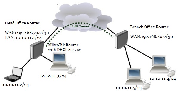
EoIP VPN for LAN Bridging
In this network, Head Office Router is connected to internet through ether1 interface having IP address 192.168.70.2/30. In your real network this IP address will be replaced with public IP address provided by your ISP. Head Office Router’s ether2 interface is connected to local network. After EoIP tunnel configuration, an EoIP tunnel interface will be created in Head Office Router. We will create a bridge interface where we will enable a DHCP server whose network will be 10.10.11.0/24 and we will add ether2 interface and EoIP tunnel interface into this bridge network so that Head Office LAN and Branch Office LAN can keep at the same broadcast domain and DHCP server can be accessible from the both LANs.
Similarly, Branch Office Router is connected to internet through ether1 interface having IP address 192.168.80.2/30. In your real network this IP address will also be replaced with public IP address. Branch Office Router’s ether2 interface is connected to local network. After EoIP tunnel configuration, an EoIP tunnel interface will also be created in Branch Office Router. We will create a bridge interface and add ether2 interface and EoIP tunnel interface into this bridge network so that Head Office LAN and Branch Office LAN can keep at the same broadcast domain and DHCP server can be accessible from Branch Office LAN.
EoIP Tunnel Configuration for Bridging LANs over the Internet
We will now start our EoIP Tunnel configuration that will bridge our Head Office LAN and Branch Office LAN. Complete EoIP Tunnel configuration according to above network diagram can be divided into two parts.
Head Office Router configuration for EoIP Tunnel
Branch Office Router configuration for EoIP Tunnel
Part 1: Head Office Router Configuration for EoIP Tunnel
Head Office Router is our core router where DHCP Server will be enabled and Branch Office Router will access this DHCP Server across EoIP Tunnel. Head Office Router configuration for EoIP tunnel can be completed within the following four steps.
RouterOS basic configuration
EoIP Tunnel configuration
Bridge Configuration
DHCP server configuration
Step 1: Head Office RouterOS Basic Configuration
Basic RouterOS configuration includes assigning WAN IP, DNS IP and Route, NAT configuration. The following steps will guide you how to perform basic configuration in Head Office RouterOS.
Login to Head Office RouterOS using winbox and go to IP > Addresses. In Address List window, click on PLUS SIGN (+). In New Address window, put WAN IP address (192.168.70.2/30) in Address input field and choose WAN interface (ether1) from Interface dropdown menu and click on Apply and OK button.
Go to IP > DNS and put DNS servers IP (8.8.8.8 or 8.8.4.4) in Servers input field and click on Apply and OK button.
Go to IP > Firewall and click on NAT tab and then click on PLUS SIGN (+). Under General tab, choose srcnat from Chain dropdown menu and click on Action tab and then choose masquerade from Action dropdown menu. Click on Apply and OK button.
Go to IP > Routes and click on PLUS SIGN (+). In New Route window, click on Gateway input field and put WAN Gateway address (192.168.70.1) in Gateway input field and click on Apply and OK button.
Basic RouterOS configuration has been completed in Head Office Router. Now we will configure EoIP Tunnel in Head Office Router.
Step 2: EoIP Tunnel Configuration in Head Office Router
The following steps will show how to configure EoIP tunnel in your Head Office Router.
Click on Interfaces menu item from Winbox and click on EoIP Tunnel tab and then click on PLUS SIGN (+). New Interface window will appear.
Put a meaningful EoIP tunnel interface name (eoip-tunnel-r1) in Name input field.
Put Head Office Router’s WAN IP address (192.168.70.2) in Local Address input field.
Put Branch Office Router’s WAN IP address (192.168.80.2) in Remote Address input field.
Put a unique ID (for example: 10) in Tunnel ID input field. This ID must be same in both routers.
Click Apply and OK button.
You will find a new EoIP tunnel interface followed by your given name (eoip-tunnel-r1) has been created in Interface List window.
EoIP tunnel configuration in Head Office Router has been completed. Now we will configure bridge in Head Office Router.
Step 3: Bridge Configuration in Head Office Router
By default every interface of MikroTik Router keeps separate broadcast domain that means every port is layer3 port. But we want to keep EoIP tunnel interface and LAN interface at the same broadcast domain. So, we have to turn layer3 port to layer2 port. MikroTik Bridging feature helps to turn layer3 port as layer2 port logically. The following steps will guide you how to configure MikroTik Bridge to keep EoIP tunnel interface and LAN interface at the same broadcast domain.
Click on Bridge menu item from left menu bar. Bridge window will appear now.
Click on Bridge tab and then click on PLUS SIGN (+). New Interface window will appear.
Put your bridge interface name (example: LAN-bridge) as you wish in the Name input field.
Click Apply and OK button.
Now click on Ports tab and then click on PLUS SIGN (+). New Bridge Port window will appear.
Choose EoIP tunnel interface (eoip-tunnel-r1) from Interface dropdown menu.
Choose your Bridge interface (LAN-bridge) that you created before from Bridge dropdown menu.
Click Apply and OK button.
Similarly, click on PLUS SIGN (+) again and choose LAN interface (ether2) from Interface dropdown menu.
Choose your Bridge interface (LAN-bridge) from Bridge dropdown menu.
Click Apply and OK button.
Bridge configuration has been completed. As EoIP Tunnel interface and ether2 interface are layer2 port now, we cannot assign IP in these ports. But Bridge interface is now layer3 port. So, we will assign our LAN IP on this bridge interface.
Go to IP > Addresses. In Address List window, click on PLUS SIGN (+). In New Address window, put LAN IP address (10.10.11.1/24) in Address input field and choose Bridge interface (LAN-bridge) from Interface dropdown menu and click on Apply and OK button.
Bridge configuration in Head Office Router has been completed. Now we will configure DHCP Server so that LAN workstations get IP address dynamically.
Step 4: DHCP Server Configuration in Head Office Router
In Head Office Router, we will configure DHCP Server so that Head Office LAN workstations as well as Branch Office LAN workstations get IP address dynamically from this DHCP Server. The following steps will show you how to configure DHCP Server in MikroTik RouterOS.
Go to IP > DHCP Servermenu from Winbox. DHCP Server window will appear.
InDHCP Server window, click on DHCP Setup button and choose the interface (in this article: LAN-bridge) on which you want to setup DHCP server from DHCP Server Interface drop-down menu and then click on Next
Now put your LAN network block (10.10.11.0/24) in DHCP Address Space input box and click Next DHCP client/LAN user will get IP from this network.
Choose gateway address (10.10.11.1) for the given network in Gateway for DHCP Networkinput box and then click Next
Provide IP range from which your DHCP client/LAN user will get IP in Address to Give Outinput box and click Next
Provide preferred DNS server IP and click Next
Now provide IP lease time and click Next Default lease time is 3 days.
DHCP setup will be completed now and a successful message will be shown.
Now connect any IP device (Desktop, Laptop, Smartphone etc.) to your network. Automatically an IP will be allocated for that device from your MikroTik DHCP server. Click Leases tab and observe IP lease status of that DHCP client.
DHCP Server configuration in Head Office Router has been completed. We will now configure Branch Office Router so that Branch Office LAN workstation can get IP from this DHCP Server.
Part 2: Branch Office Router configuration for EoIP Tunnel
Branch Office Router will be used to create just EoIP Tunnel. There is no extra configuration without EoIP Tunnel related configuration. Complete EoIP Tunnel configuration in Branch Office Router can be divided into three steps.
Basic RouterOS Configuration
EoIP Tunnel Configuration
Bridge Configuration
Step 1: Branch Office Router Basic Configuration
Basic RouterOS configuration includes assigning WAN IP, LAN, DNS IP and Route, NAT configuration. But in Branch Office Router we will only assign WAN IP and Gateway IP. The following steps will show how to assign WAN IP and Gateway IP in Branch Office Router.
Login to Branch Office RouterOS using winbox and go to IP > Addresses. In Address List window, click on PLUS SIGN (+). In New Address window, put WAN IP address (192.168.80.2/30) in Address input field and choose WAN interface (ether1) from Interface dropdown menu and click on Apply and OK button.
Go to IP > Routes and click on PLUS SIGN (+). In New Route window, click on Gateway input field and put WAN Gateway address (192.168.80.1) in Gateway input field and click on Apply and OK button.
Basic RouterOS configuration in Branch Office Router has been completed. Now we configure EoIP Tunnel in Branch Office Router.
Step 2: EoIP Tunnel Configuration in Branch Office Router
The following steps will show how to configure EoIP tunnel in your Branch Office Router.
Click on Interfaces menu item from Winbox and click on EoIP Tunnel tab and then click on PLUS SIGN (+). New Interface window will appear.
Put a meaningful EoIP tunnel interface name (eoip-tunnel-r2) in Name input field.
Put Branch Office Router’s WAN IP address (192.168.80.2) in Local Address input field.
Put Head Office Router’s WAN IP address (192.168.70.2) in Remote Address input field.
Put same unique ID (in this article: 10) that you provide in Head Office Router in Tunnel ID input field.
Click Apply and OK button. You will find a new EoIP tunnel interface followed by your given name (eoip-tunnel-r2) has been created in Interface List window.
EoIP tunnel configuration in Branch Office Router has been completed. Now we will configure bridge in Branch Office Router so that LAN Interface and EoIP Tunnel Interface keep at the same broadcast domain.
Step 3: Bridge Configuration in Branch Office Router
The following steps will guide you how to configure MikroTik Bridge to keep EoIP tunnel interface and LAN interface at the same broadcast domain.
Click on Bridge menu item from left menu bar. Bridge window will appear now.
Click on Bridge tab and then click on PLUS SIGN (+). New Interface window will appear.
Put your bridge interface name (example: LAN-bridge) as you wish in the Name input field.
Click Apply and OK button.
Now click on Ports tab and then click on PLUS SIGN (+). New Bridge Port window will appear.
Choose EoIP tunnel interface (eoip-tunnel-r2) from Interface dropdown menu.
Choose your Bridge interface (LAN-bridge) that you created before from Bridge dropdown menu.
Click Apply and OK button.
Similarly, click on PLUS SIGN (+) again and choose LAN interface (ether2) from Interface dropdown menu.
Choose your Bridge interface (LAN-bridge) from Bridge dropdown menu.
Click Apply and OK button.
Bridge configuration in Branch Office Router has been completed. Now Branch Office Network and Head Office Network are in the same broadcast domain over the internet and both Office network will be capable to get IP address from Head Office DHCP Server.
Connect any workstation from Branch Office Router and if everything is OK, the workstation will get an IP address dynamically from DHCP Server and will be capable to access any workstation or server of Head Office Network.
MikroTik EoIP Tunnel Configuration for Bridging LANs over the Internet has been explained step by step in this article. I hope will now be able to configure EoIP Tunnel for bridging LAN over the Internet. However, if you face any problem to configure EoIP Tunnel, feel free to discuss in comment or contact with me from Contact page. I will try my best stay with you.
I guess, you have purchased a new MikroTik Router or installed a new MikroTik RouterOS on PC and you are searching How to Start MikroTik Router First Time and How to Complete Basic RouterOS Configuration using WebFig (Web Interface) for running a basic network. If these are your concern, don’t worry, in this article I will show how to startup your MikroTik Router first time and complete RouterOS basic configuration using WebFig web interface so easily.
There are three methods to startup and configure a new MikroTik Router.
MikroTik First Time Startup and Configuration using Winbox: Winbox configuration utility is able to connect to the MikroTik Router via MAC address or IP address. Winbox is a graphical utility. So, it can be helpful for a new MikroTik user as well as for those users who like to configure RouterOS with Graphical Window.
MikroTik First Time Startup and Configuration using WebFig: WebFig is a web configuration utility for MikroTik Router. Those who like to configure MikroTik Router with web Interface can use WebFig utility. It has almost the same configuration functionality as Winbox.
MikroTik First Time Startup and Configuration using CLI: Command Line Interface (CLI) utility gives facility to configure MikroTik Router using text commands. There are several ways to access MikroTik CLI such as Winbox terminal, Telnet, SSH, serial cable etc.
The goal of this article is to setup MikroTik Router first time with WebFig web interface. So, the following section will show how to startup and configure MikroTik Router first time using WebFig web interface.
Core Devices and IP Information
To configure a MikroTik Router first time with WebFig web interface, I am using MikroTik RouterOSv6.38.1. IP information that I am using for this basic configuration are given below.
WAN IP: 192.168.70.2/30
WAN Gateway: 192.168.70.1
LAN Gateway: 10.10.11.1/24
DNS IP: 8.8.8.8 and 8.8.4.4
This IP information is just for my RND purpose. Change this information according to your network requirements.
MikroTik Router First Time Startup and Configuration using WebFig
Web interface is one of the most popular methods to configure and maintain network devices. Most of the people feel comfort to maintain their devices with web interface. For this, MikroTik Router introduces WebFig web interface to configure and maintain MikroTik RouterOS.
MikroTik RouterOS configuration with WebFig can be divided into two parts.
Part 1: Connecting and login to MikroTik Router first time and
Part 2: MikroTik Router basic configuration using WebFig.
Part 1: Connecting and login to MikroTik Router First Time
MikroTik RouterOS comes with default IP address 192.168.88.1/24 assigned on the first interface (ether1 port). So, WebFig web interface can be accessible typing this IP address in a web browser. The following steps will show you how to access WebFig web interface using the default IP address from windows operating system.
Power on your MikroTik Router and connect your MikroTik Router’s ether1 port (first interface) and laptop or desktop’s LAN port with a RJ45 cable.
From windows operating system go to Control Panel > Network and Sharing Center > Change adapter settings. Network Connections window will appear.
From Network Connections window, click mouse right button on your LAN adaptor and then click on Properties option. Ethernet Properties window will appear.
From Ethernet Properties window, click on Internet Protocol Version 4 (TCP/IPv4) option and then click on Properties button. Internet Protocol Version 4 (TCP/IPv4) Properties window will appear.
From Internet Protocol Version 4 (TCP/IPv4) Properties, click on Use the following IP address radio button and put any IP from MikroTik default IP block (Such as 192.168.88.10) and put subnet mask (255.255.255.0). Click OK button and close all open windows.
Now open your favorite web browser such Mozilla Firefox, Google Chrome or any other browsers and type MikroTik default IP (https://192.168.88.1) in URL bar and hit Enter key. If everything is OK, Quick Setup page will appear now because MikroTik Router default and only user is admin which has no password. So, no authentication is required until user is configured. We will do nothing in Quick Setup page but configure user first. MikroTik default user is admin and keeping known admin user is not so secure because hacking probability keeps 50% in this case. So, we will first create an administrator user who can control MikroTik Router fully and then delete admin user.
Go to System > Users page and click on Add New button. Put a new username in Name input field and choose full option from Group dropdown menu. Put a strong password in Password input field and retype your Password in Confirm Password field. Now click Apply and OK button.
After creating a full access user, we are now eligible to delete admin user. Click on admin user and then click on Remove button. The admin user will be deleted now.
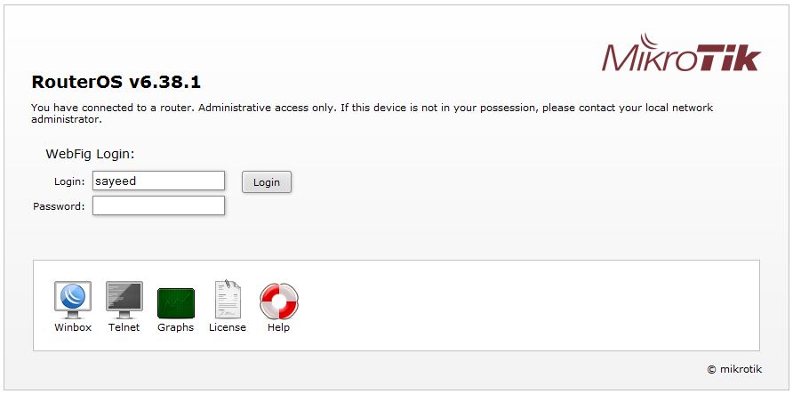
Click on Logout button and you will now find WebFig login prompt like below image.
Put your newly created username in Login input field and password in Password input field and then click on Login button to get WegFig configuration page.
MikroTik WebFig Login Page
We have successfully configured MikroTik users and login to MikroTik WebFig web interface. Now we will do MikroTik Router basic configuration from this web interface.
Part 2: MikroTik Router Basic Configuration using WebFig
MikroTik Router basic configuration includes assigning WAN, LAN and DNS IP and configuring NAT and Route. The following steps will show how to do basic configuration in your RouterOS using WebFig web interface.
Go to IP > Addresses page. Click on default IP address. Now put LAN Gateway IP (10.10.11.1/24) in Address input field and put a meaningful comment (LAN Interface) in Comment input field and click Apply and OK button.
Assign a LAN IP in your laptop or desktop again because we have changed MikroTik’s default IP address and type LAN Gateway IP (https://10.10.11.1) in your browser. You will find login page now. Login with your username and password again.
Go to IP > Address page and click on Add New button. In New Address page, put WAN IP (192.168.70.2/30) in Address input field and choose ether2 from dropdown. Put a meaningful comment (WAN Interface) in Comment input field. Click on Apply and OK button.
Go to IP > DNS page and put DNS servers IP (8.8.8.8 and 8.8.4.4) in Servers input field and click on Apply and OK button.
Go to IP > Firewall page and click on NAT tab and then click on Add New button. Under General panel, choose srcnat from Chain dropdown menu and go to Action panel and then choose masquerade from Action dropdown menu. Click on Apply and OK button.
Go to IP > Routes page and click on Add New button. In New Route page, click on Gateway arrow button and put WAN Gateway address (192.168.70.1) in Gateway input field and click on Apply and OK button.
Your MikroTik router is completely ready if you follow the above 4 steps carefully. Connect a switch to MikroTik LAN interface (ether1) with RJ45 cable and connect all PCs to this switch. Also connect ISP cable to WAN interface (ether2). Now assign IP to all your LAN PCs according to your LAN IP network series. If you face any problem to set IP address in windows PC, follow my another article about how to assign static IP address in windows operating system which will guide you the proper way to assign IP address in any windows PC. Now browse any website or ping google.com from any your LAN PC. If your ISP is OK, you will now be able to browse any website successfully.
MikroTik Router basic configuration is not so enough to maintain a real network. If you need to maintain an office network, it will be better to use MikroTik DHCP Server. Managing DHCP Server with Radius Server will provide you more faster and smart solution.
MikroTik Router First Time Startup and Configuration using WebFig web interfacehas been explained step by step in this article. I hope, you are now able to configure a new MikroTik Router successfully from very beginning with WebFig web interface. However, if you face any problem to configure your MikroTik Router first time, feel free to discuss in comment or contact with me from Contact page. I will try my best to stay with you.