MikroTik Router usually sits between untrusted public network and trusted local network. So, it is so important to apply security in MikroTik Router otherwise MikroTik Router can be compromised by the hackers. There are various firewall techniques in MikroTik RouterOS those can be applied to secure MikroTik Router. In my previous articles, I discussed how to harden MikroTik RouterOS with restricting login services and restricting MikroTik login users. In this article I will discuss how to secure MikroTik RouterOS with Port Knowing.
Port Knocking
Port knocking is a method that enables access to the router only after receiving a sequenced connection attempts on a set of prespecified closed ports. Once the correct sequence of the connection attempts is received, the RouterOS dynamically adds the knocking host source IP to the allowed address list and the allowed host will be able to connect to MikroTik Router.
In port knocking method, all incoming requests are kept blocked and only the correct sequence maintained host is allowed to MikroTik Router. Hackers usually cannot scan the router and cannot do brute forcing. So, MikroTik Router keeps safe by implementing port knocking method.
How to Implement Port Knocking in MikroTik Router
It is so easy to implement port knocking in MikroTik RouterOS. MikroTik Firewall is enough to implement port knocking in RouterOS. Applying the following four firewall rules, a simple port knocking system can be implemented in MikroTik RouterOS. It is also possible to make more complex port knocking system although.
Rule 1: Creating First Port Knocking Firewall Rule
In the first firewall rule, we will create a firewall filter rule that will add the knocking host IP address to an address list if any host knocked on TCP port 9000. You can use any TCP or UDP port. I am using TCP port 9000 for this article configuration. The following steps will show how to create first knocking firewall rule in MikroTik RouterOS.
- Login to MikroTik Router with Winbox using full permission user credential.
- Go to IP > Firewall menu item. Firewall window will appear.
- Click on Filter Rules and then click on PLUS SIGN (+). New Filter Rule window will appear.
- Click on General tab and choose input from Chain drop down menu. Click on Protocol drop down menu and choose 6(tcp) and then put 9000 in Dst. Port input box.
- From Action drop down menu, choose add src to address list option and put address list name (example: port:9000) in Address List input box and then put 1m duration(00:01:00) in Timeout input box. So, it will wait one minute to get second legitimate port knocking.
- Click Apply and OK button.

First port knocking firewall rule has been created. We will now create second firewall rule to determine legitimate host.
Rule 2: Creating Second Port Knocking Firewall Rule
After creating first port knocking firewall rule, we will now create second port knocking rule that will add the knocking host IP address to another address list if the knocked host IP address was listed in the previous address list and the knocking port is TCP port 8000 [You can use any TCP or UDP port here]. The following steps will show how to create firewall rule to get second port knocking.
- Click on Filter Rules tab again and then click on PLUS SIGN (+). New Filter Rule window will appear.
- Click on General tab and choose input from Chain drop down menu. Click on Protocol drop down and choose 6(tcp) and then put 8000 in Dst. Port input box.
- From Advanced tab, choose the previous address list (port:9000, that we created in Rule 1) from Src. Address List drop down menu.
- From Action drop down menu, choose add src to address list option and put address list name (example: secure) in Address List input box and then put 30m duration(00:30:00) in Timeout input box. So, the host can use MikroTik RouterOS for 30 minutes.
- Click Apply and OK button.

Second port knocking rule has also been created. Now if any host send request on TCP port 9000 and then TCP port 8000, the host IP will be added in secure address list. We will now create third firewall rule that will allow access if the host IP keeps in secure address list.
Rule 3: Allowing Host That Knocked Maintaining Correct Sequence
We will now allow that host which will follow correct port knocking sequence. From the above two rules, we can see that if any host follow correct sequence, the host will be added to secure address list. Now we will allow the host which is in secure address list. The following steps will show how to allow host which is in secure address list.
- Click on Filter Rules tab again and then click on PLUS SING (+). New Filter Rule window will appear.
- From General tab, chose input from Chain drop down menu.
- From Advanced tab, choose secure from Src. Address List drop down menu.
- From Action tab, choose accept from Action drop down menu.
- Click Apply and OK button.
With this firewall rule, only those hosts will get access which will keep in secure address list. Now we will create another firewall rule that will block any request that will try to access in MikroTik RouterOS.
Rule 4: Creating Access Blocking Rule
We will now create the last firewall rule that will block any incoming request which is not in secure address list group. The following steps will show how to create blocking firewall rule in MikroTik RouterOS.
- Click on Filters Rules tab and then click on PLUS SIGN (+). New Filter Rule window will appear.
- From General tab, choose input from Chain drop down menu.
- From Action tab, choose drop from Action drop down menu.
- Click Apply and OK button.
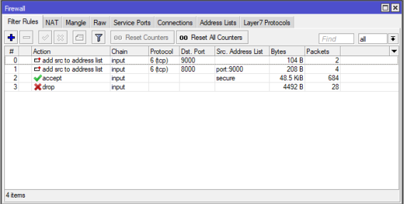
So, now any incoming request will be dropped except those who are in secure address list group. Make sure the created rules are in the following order otherwise port knocking will not work.
After creating the above rule, your Winbox will be disconnected and cannot be logged in until port knocking. So, we have to now know how to do port knocking in MikroTik Router. In the following section we will learn how to do port knocking in MikroTik Router OS.
Port Knocking Methods in MikroTik RouterOS
There are a lot of methods those can be applied to do port knocking. Among these, I will mention only three simple and easy port knocking methods here.
Method 1: Port Knocking from Browser
Web Browser is the basic and easiest port knocking client. Just open your favorite web browser and type Router IP address and Port combination [http://ip_address:port_number] in the URL bar. Your browser will do port knocking and you will be able to do logged in MikroTik Router. Make sure you have followed the correct port sequence. For example, according to our above configuration, first type https://ip_address:9000 and hit enter key and then type http://ip_address:8000 within one minute and then hit enter key. After successful port knocking, dynamic address list will be created like the following image.

Method 2: Port Knocking from Winbox
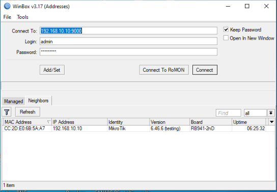
Winbox can also be used to do port knocking. Open winbox and type ip_address:port_number combination in Connect To input box and then click Connect button. Winbox will do port knocking and you will be able to connect MikroTik Router. Make sure you are following the correct port sequence.
Method 3: Port Knocking with Windows Port Knocking Application
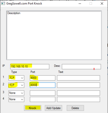
Greg Sowell provides a windows based port knock application which is amazing. Download [http://gregsowell.com/?download=5695] port knock application from their website and unzip it. If it asks to provide password, put portknock. Run the application and provide IP address and port sequence and then hit Knock button. It will do port knocking and you will be able to login to MikroTik Router.
How to secure MikroTik Router with Port Knocking has been discussed in this article. I hope, you will now be able to implement port knocking in MikroTik Router. However, if you face any confusion to implement port knocking, feel free to discuss in comment or contact me from Contact page. I will try my best to stay with you.