Access List is an amazing feature in MikroTik Wireless Router. This feature helps to allow only any specific MAC address in MikroTik WiFi AP. So, a MAC address filtering WiFi Access Point can easily be established with MikroTik Wireless Router. In my previous article I discussed how to configure basic WiFi AP in MikroTik Wireless Router. I also discussed how to configure virtual AP on a physical wireless interface. In this article, I will show how to filter device MAC address in MikroTik WiFi AP so that any unauthenticated device cannot be connected in your network although he/she knows your WiFi SSID and password.
Enabling MAC Filtering in MikroTik WiFi AP
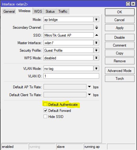
Default Authentication is enabled by default in MikroTik WiFi. Anyone can be connected to Default Authentication enabled WiFi AP just knowing the WiFi SSID and Password. So, first we have to disable Default Authentication so that WiFi AP checks MAC address along with SSID and Password authentication. The following steps will show how to disable Default Authentication mode in MikroTik Wireless Router.
Login to MikroTik Wireless Router using Winbox with full permission user.
From Winbox, click on Wireless menu item. Wireless Tables window will appear.
In WiFi Interfaces tab, you will find available wireless interfaces both Physical and Virtual interface where WiFi AP has been configured.
Double click on a desired interface where WiFi AP has been configured and want to enable MAC Filtering. Interface window will appear.
Click on Wireless tab and then uncheck Default Authenticate checkbox.
Click Apply and OK button.
Disabling Default Authentication in WiFi AP
Doing the above steps MikroTik WiFi AP will turn into MAC address filtering WiFi AP. So, anyone cannot be connected to WiFi AP without providing MAC address although he/she knows SSID and Password.
In MAC address filtering WiFi AP, The AP will first check whether any device which is eager to connect is allowed in Access List or not. If the device is allowed in Access List, it will be able to connect to WiFi AP otherwise it will be denied.
So, if we want to allow any device, we have to put the device MAC address in Access List. The next part will show how to put device MAC address in MikroTik WiFi Access List.
Putting MAC Address in WiFi Access List
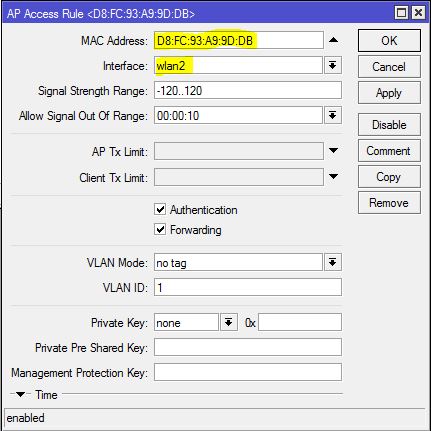
After disabling Default Authentication in MikroTik WiFi AP, we have to put any desired device MAC address in Access List otherwise the device cannot be connected to WiFi AP. The following steps will show how to add device MAC address in MikroTik WiFi Access List.
From Wireless Tables window, click on Access List tab and then click on PLUS SIGN (+). New AP Access Rule window will appear.
Put the device MAC address (example: D8:FC:93:A9:9D:DB) in MAC Address input field.
Choose the wireless interface (example: wlan2) where MAC address filtering WiFi AP has been configured from Interface drop down menu.
Optionally you can set a private password for any device in Private Pre Shared Key input box so that the device can be connected with this special password.
Click Apply and OK button.
Putting MAC Address in WiFi Access List
Similarly, we have to provide other devices MAC addresses which want to connect to WiFi AP.
How to Configure a MAC Address Filtering WiFi AP in MikroTik Wireless Router has been discussed in this article. I hope, you will now be able to configure a MAC address filtering WiFi AP with MikroTik Wireless Router. However, if you face any confusion to configure MAC filtering WiFi AP, feel free to discuss in comment or contact with me from Contact page. I will try my best to stay with you.
Как известно, благодаря Всемирной паутине пользователи способны обмениваться всевозможными файлами на любом расстоянии, достаточно лишь иметь в своём распоряжении интернет-подключение. Однако такой файлообмен осуществляется через интернет-провайдера, т. е. публичную сеть. Но что же делать в том случае, когда пользователям необходимо переслать личные данные напрямую друг другу, в обход сетевых посредников. В этой ситуации на помощь может прийти локальная сеть — специальное закрытое сетевое подключение для защищённой передачи данных. Одной из разновидностей подключения по локальной сети является Wi-Fi-мост.
One of the most amazing features of MikroTik Wireless Router is creating Multiple SSID (Virtual AP) on a physical wireless interface. So, creating a Guest WiFi AP with separate LAN block, SSID and DHCP Server is so easy using MikroTik WiFi AP Router. In the previous article, I discussed how to configure MikroTik WiFi Access Point on physical wireless interface with DHCP Server using hAP Lite (RB941-2nD) Wireless Router. In this article I will discuss how to configure a Virtual WiFi AP on the physical interface with another SSID, LAN block and DHCP Server for guest wireless devices.
Network Diagram
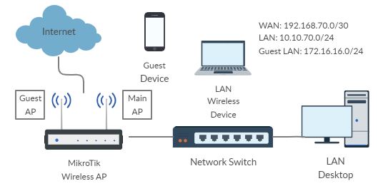
The following network diagram is being followed for this article configuration.
MikroTik Virtual AP Configuration
In this network diagram, hAP lite MikroTik Wireless Router is being used as a WiFi AP and LAN gateway. This wireless router has one WLAN interface and four Ethernet interfaces. WiFi AP has been created on WLAN interface so that wireless devices can be connected. We will now create another Virtual WiFi AP with separate SSID on this WLAN interface creating a virtual WLAN interface. The virtual WiFi AP will be used as Guest WiFi AP so that guest user can be connected with this different SSID and security key.
Among four Ethernet interfaces, ether1 port is being used as WAN connection with IP network 192.168.70.0/30. A bridge interface (named LAN_Bridge) has been created and a DHCP Server (with IP block 10.10.70.0/24) has also been configured on this bridge interface. The WLAN interface and ether2 to ether4 interfaces are now under this bridge and WiFi users and LAN users get IP address, default gateway and other network parameters from this DHCP Server automatically.
We will now create another bridge interface (named Guest_LAN) and add created virtual WLAN interface to this bridge. We also setup DHCP Server (with IP Block: 172.16.16.1/24) on the new bridge interface so that guest devices get IP address, default gateway and other network parameters automatically and can get internet access.
MikroTik Virtual AP Configuration with DHCP Server
We will now configure Virtual WiFi AP with separate SSID, password and LAN in MikroTik hAP light Wireless Router. Complete Virtual Wireless AP Setup can be divided into the following four steps.
Virtual WiFi AP Setup on Virtual WLAN Interface
Creating Bridge Interface and Adding Virtual WLAN Interface
Assigning Guest Block Gateway IP and NATing Configuration
DHCP Server Configuration on Guest Bridge Interface
Step 1: Virtual WiFi AP Setup on Virtual WLAN Interface
MikroTik hAP lite wireless router has a WLAN interface where WiFi AP has to be setup. MikroTik Wireless Router also supports creating virtual WLAN interface on a physical WLAN interface and Virtual WiFi can also setup on this virtual WLAN interface. Like WiFi setup on physical WLAN interface, we have to first create Security Profile and then create SSID on virtual WLAN interface to connect guest wireless devices.
Creating Security Profiles for Guest WiFi Access Point
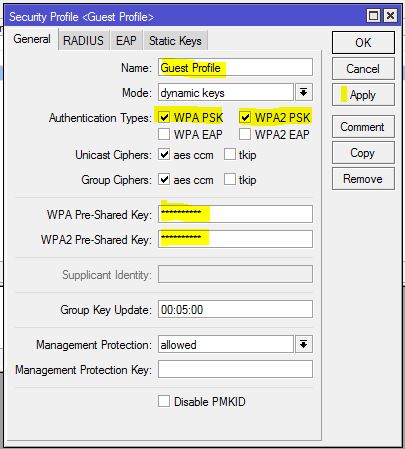
To connect a wireless device with MikroTik Virtual WiFi AP, guest wireless devices must provide security key (password). MikroTik wireless supports both WPA PSK and WPA2 PSK authentication type. The following steps will show how to create passkey for MikroTik Virtual WiFi AP with Security Profile.
From Winbox, click on Wireless menu item. Wireless Tables window will appear.
Click on Security Profiles tab and then click on PLUS SIGN (+). New Security Profile window will appear.
Put a meaningful profile name (Guest Profile) in Name input field.
Choose dynamic keys from Mode drop down menu.
Check WPA PSK and WPA2 PSK checkbox from Authentication Types panel.
Now provide strong password in WPA Pre-Shared Key and WPA2 Pre-Shared Key password box.
Click Apply and OK button.
Guest WiFi Security Profile
Creating Separate SSID for MikroTik Virtual WiFi AP
After creating Security Profile for Virtual WiFi AP, we have to first create virtual WLAN Interface and then set SSID (Service Set Identifier) on virtual WLAN interface so that guest or desired wireless devices can find MikroTik Virtual Access Point with created SSID. The following steps will show how to create virtual WLAN interface and set SSID in hAP lite MikroTik Wireless Router.
Click on WiFi Interfaces tab and you will find physical WLAN interface (by default: wlan1) here.
Click on PLUS SIGN (+) dropdown and then click on Virtual option. New Interface window will appear.
From General tab you can set WiFi interface name from Name input box or you can keep it default (wlan2).
Click on Wireless tab and choose ap bridge from Mode dropdown menu.
Put SSID name (MikroTik Guest AP) in SSID input box.
Choose physical WLAN interface from Master Interface dropdown menu.
Choose created security profile (Guest Profile) from Security Profile drop down menu.
Make sure Default Authenticate and Default Forward checkbox is checked. Otherwise devices will not be connected until MAC authentication.
Click Apply and OK button.
You will find Virtual WLAN interface (wlan2) will be created under physical WLAN interface.
Virtual WLAN Interface in MikroTik Wireless Router
Now created SSID will be found in wireless devices and wireless device can be connected providing password. MikroTik ap bridge mode allows 2007 wireless device connections. Theoretically you can create 2007 Virtual WiFi AP also. But in real network it is not good to create more than 25-30 Virtual APs. If you create more virtual AP, Wireless performance will be degraded.
You will find connected devices in Registration tab. But connection is not enough to get internet. IP address, default gateway and other network parameters have to provide to get internet to the connected devices. So, we will now assign separate LAN gateway creating new bridge interface. We will also configure another DHCP Server on bridge interface from where assign IP address, default gateway and other network parameters will be assigned automatically to guest wireless devices.
Step 2: Creating New Bridge Interface and Adding Virtual WLAN Interface
We will now create a new bridge interface and add virtual WLAN interface to this bridge. The following steps will show how to create bridge interface and add virtual WLAN interface to it.
Click on Bridge menu item. Bridge window will appear.
Click on Bridge tab and then click on PLUS SIGN (+). New Interface window will appear.
Put bridge interface name (Guest_LAN) in Name input field.
Click Apply and OK button.
Now click on Ports tab and click on PLUS SIGN (+). New Bridge Port window will appear.
Choose wlan2 interface from Interface dropdown menu.
Choose created bridge interface (Guest_LAN) from Bridge dropdown menu.
Click Apply and OK button.
New bridge interface has been created and virtual WLAN interface is also added to this bridge. So, any configuration will be done on bridge interface will be applied to Virtual WLAN interface and Virtual WiFi AP.
Step 3: Assigning Guest Block Gateway IP and NATing Configuration
We will now assign guest block Gateway IP on new bridge interface and configure NATing. The following steps will show how to assign LAN gateway IP and do NATing in MikroTik Wireless Router.
Go to IP > Address menu item. Address List window will appear.
Click on PLUS SIGN (+) and put guest block LAN Gateway IP (172.16.16.1/24) in Address input field and choose new bridge interface (Guest_LAN) from Interface dropdown menu and click Apply and OK button.
Go to IP > Firewall menu item. Firewall window will appear. Click on NAT tab and then click on PLUS SIGN (+). New NAT Rule window will appear. From General tab choose srcnat from Chain drop down menu and put guest LAN Block (172.16.16.0/24) in Src. Address input field. Click on Action tab and choose masquerade from Action drop down menu and then click Apply and OK button.
Assigning LAN gateway IP and NATing configuration has been completed. We will now setup another DHCP Server on new bridge interface so that connected guest wireless devices can get IP address, default gateway and other network parameters automatically from this new DHCP Server.
Step 4: DHCP Server Configuration on New Bridge Interface
We will now setup another DHCP Server on new bridge interface so that Guest WiFi users can get IP address, default gateway and other network parameters automatically. The following steps will show how to setup DHCP Server on new bridge interface in MikroTik Wireless RouterOS.
Go to IP > DHCP Server menu item. DHCP Server window will appear.
Click on DHCP Setup button. DHCP Setup window will appear.
Choose new bridge interface (Guest_LAN) from DHCP Server Interface drop down menu and then click Next button.
LAN Block (172.16.16.0/24) will be automatically assigned in DHCP Address Space input field. So, nothing to do. Just click Next button.
LAN Gateway IP (172.16.16.1) will automatically be assigned in Gateway for DHCP Network input field. So, just click Next button.
IP Pool from where IP address will be assigned to Guest Wireless devices will be automatically assigned from Guest LAN Block (172.16.16.2-172.16.16.254) in Addresses to Give Out input field. So, just click Next button.
Your assigned DNS Server IP will automatically be assigned in DNS Server input filed. So, click Next button.
Default DHCP lease time is 10 minute. So, 10 minute will keep assigned in Lease Time input filed. If you want, you can increase lease time for guest users as much you want. Click Next button.
Now you will find DHCP Setup successful message window. Just click OK button.
Separate DHCP Server with Separate LAN
MikroTik Guest WiFi AP with DHCP Server is now ready. Now connect any guest or any wireless device. The device will get IP address, default gateway and other network parameters automatically and be able to get internet access.
With this MikroTik WiFi AP configuration any wireless user who knows WiFi password can connect with SSID and can able to get access to DHCP Server and DHCP Server will be happy to provide him/her IP address, default gateway and other network parameters because there is no filter rule to block unauthorized access. MikroTik Wireless or WiFi AP is smart enough granting access based on MAC address. But must configure MAC address filtering WiFi AP which will be discussed in my next article.
How to Configure MikroTik Virtual WiFi AP with DHCP Server in hAP lite Wireless Router has been discussed in this article. I hope you will now be able to configure Virtual WiFi AP in MikroTik Wireless Router following the above steps properly. However, if you face any confusion to follow the above steps properly, feel free to discuss in comment or contact with me from Contact page. I will try my best to stay with you.
MikroTik Wireless Router is one of the most popular and stable WiFi Routers. WiFi Zone for an ISP or for an office or for a home can easily be configured with MikroTik WiFi Router. MikroTik has a lot of WiFi Routers that can be used as a WiFi Access Point (AP), a WiFi Station or a WiFi Repeater. MikroTik Wireless Router can also be used as both WiFi Station and WiFi AP simultaneously. The simple usage of MikroTik Wireless Router is to create a WiFi Zone with MikroTik WiFi AP. So, in this article I will discuss how to configure MikroTik WiFi AP to create a WiFi Zone in a home or in an office or even in an ISP network using MikroTik hAP lite wireless router.
MikroTik WiFi Access Point
The bridge or ap-bridge mode of a MikroTik Wireless Router is used to create a WiFi Access Point. MikroTik Wireless Router offers creating meaningful SSID with WPA and WPA2 PSK security. MAC Address filtering can also be applied in MikroTik WiFi AP with Access List and RADIUS Server. A lot of WiFi Routers are available in MikroTik for different purpose. Among these we will configure a hAP lite (RB941-2nD) wireless router (but the configuration can be same for all MikroTik Wireless Routers) to create a WiFi Zone in a home, office or ISP.
Network Diagram
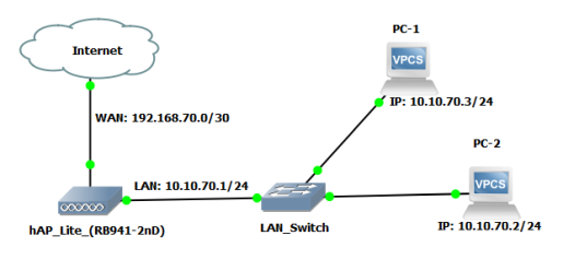
The following network diagram is being followed for this article configuration.
MikroTik WiFi Router
In this network diagram a hAP lite MikroTik Wireless Router is being used as a WiFi AP and LAN gateway. This wireless router has one WLAN interface and four Ethernet interfaces. WiFi AP will be created on WLAN interface so that wireless devices can be connected. Among four Ethernet interfaces, ether1 port will be used as WAN connection with IP network 192.168.70.0/30. We will create a bridge interface and configure a DHCP Server (with IP block 10.10.70.0/24) on this bridge interface and then add WLAN interface and ether2 to ether4 interfaces to this bridge so that WiFi users and LAN users can get IP address, default gateway and other network parameters from this DHCP Server automatically.
MikroTik WiFi AP Configuration
We will now configure WiFi AP and LAN gateway in MikroTik hAP light Wireless Router. Complete Wireless AP Setup and LAN Gateway Configuration can be divided into the following five steps.
Resetting Default RouterOS Configuration
WiFi AP Setup on WLAN Interface
Creating Bridge Interface and Adding LAN and WLAN Ports
Basic RouterOS Configuration
DHCP Configuration on Bridge Interface
Step 1: Resetting RouterOS Default Configuration
MikroTik Wireless RouterOS usually comes with default configuration. But default configuration sometimes makes you confused. So, I always suggest to reset and remove default configuration. The following steps will show how to reset and remove RouterOS default configuration.
Login to RouterOS using Winbox with admin user or any full permission user.
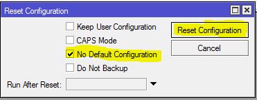
Click on System menu item and then click Reset Configuration option. Reset Configuration window will appear.
Click the No Default Configuration checkbox.
Click on Reset Configuration button. It will ask to confirm resetting configuration. Click Yes to confirm.
Now default configuration will be reset and Routerboard will be rebooted. After successful reboot, you will get a fresh and zero configuration RouterOS.
Resetting RouterOS Default Configuration
Step 2: WiFi AP Setup on WLAN Interface
MikroTik hAP lite wireless router has a WLAN interface where WiFi AP has to be setup. To setup WiFi Access Point in MikroTik Wireless Router we have to first create Security Profile and then create SSID to connect wireless devices.
Creating Security Profiles
To connect a wireless device with MikroTik WiFi AP, wireless devices must provide security key (password). MikroTik wireless supports both WPA PSK and WPA2 PSK authentication type. The following steps will show how to create passkey for MikroTik WiFi AP with Security Profile.
From Winbox, click on Wireless menu item. Wireless Tables window will appear.
Click on Security Profiles tab and then click on PLUS SIGN (+). New Security Profile window will appear.
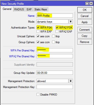
Put a meaningful profile name (WiFi Profile) in Name input field.
Choose dynamic keys from Mode drop down menu.
Check WPA PSK and WPA2 PSK checkbox from Authentication Types panel.
Now provide strong password in WPA Pre-Shared Key and WPA2 Pre-Shared Key password box.
Click Apply and OK button.
MiKroTik Wireless AP Security Profile
Creating SSID for MikroTik WiFi AP
After creating Security Profile we will now set Wireless Mode and create SSID (Service Set Identifier) so that wireless devices can find our MikroTik Access Point with created SSID. The following steps will show how to create SSID and set wireless mode in hAP lite MikroTik Wireless Router.
Click on WiFi Interfaces tab and you will find WLAN interface (by default: wlan1) here. It may be disabled at first time. So, if you find disabled, click mouse right button on it and then click on Enable option to enable WiFi interface.
Double click on available and enabled WiFi Interface. Interface window will appear.
From General tab you can set WiFi interface name from Name input box or you can keep it default.
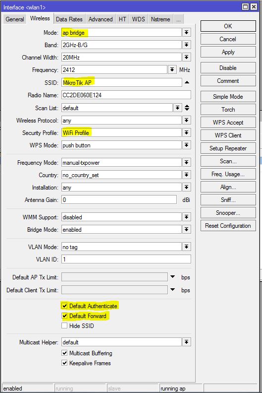
Click on Wireless tab and choose ap bridge from Mode dropdown menu.
Put SSID name (MikroTik AP) in SSID input box.
Now click on Advanced Mode button and choose your created security profile from Security Profile drop down menu.
Make sure Default Authenticate and Default Forward checkbox is checked. Otherwise devices will not be connected until MAC authentication.
Click Apply and OK button.
MikroTik WiFi AP Setup
Now created SSID will be found in wireless devices and wireless device can be connected providing password. You will find connected devices in Registration tab. But connection is not enough to get internet. IP address, default gateway and other network parameters have to provide to get internet to the connected devices. So, we will now do MikroTik Router basic configuration with creating bridge interface. We will also configure DHCP Server to assign IP address, default gateway and other network parameters automatically.
Step 3: Creating Bridge Interface and Adding LAN and WLAN Ports
We will now create a bridge interface and add ether2 to ether3 interfaces including WLAN interface to this bridge because we want to provide same block IP address to LAN and WiFi users. The following steps will show how to create bridge interface and add physical interfaces to it.
Click on Bridge menu item. Bridge interface will appear.
Click on Bridge tab and then click on PLUS SIGN (+). New Interface window will appear.
Put bridge interface name in (LAN_Bridge) Name input field.
Click Apply and OK button.
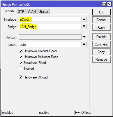
Now click on Ports tab and click on PLUS SIGN (+). New Bridge Port window will appear.
Choose ether2 interface from Interface dropdown menu.
Choose created bridge interface (LAN_Bridge) from Bridge dropdown menu.
Click Apply and OK button.
Similarly add ether3, ether4 and wlan1 interfaces to this bridge.
Adding Interface to Bridge
Step 4: Basic RouterOS Configuration
We will now do RouterOS basic configuration where we will assign WAN IP, LAN Gateway, DNS IP, and Default Gateway IP and configure NATing. The following steps will show how to do basic configuration in MikroTik Wireless Router.
Go to IP > Address menu item. Address List window will appear.
Click on PLUS SIGN (+). New Address window will appear. Put ISP provided IP address (192.168.70.2/30) in Address input box. Now choose ether1 from Interface dropdown menu. Click Apply and OK button.
Similarly, click on PLUS SIGN (+) again and put LAN Gateway IP (10.10.70.1/24) in Address input field and choose bridge interface (LAN_Bridge) from Interface dropdown menu and click Apply and OK button.
Now go to IP > DNS menu item. DNS Settings window will appear. Put your ISP provided DNS IP or Google Public DNS IP 8.8.8.8 in Servers input field.
Go to IP > Routes menu item. Route List window will appear. Click on Gateway input field and put ISP provided gateway IP (192.168.70.1) in this field. Click Apply and OK button.
Go to IP > Firewall menu item. Firewall window will appear. Click on NAT tab and then click on PLUS SIGN (+). New NAT Rule window will appear. From General tab choose srcnat from Chain drop down menu and put LAN Block (10.10.70.0/24) in Src. Address input field. Click on Action tab and choose masquerade from Action drop down menu and then click Apply and OK button.
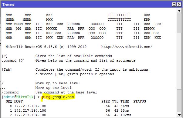
Now click New Terminal menu item and ping google.com. If everything is OK, you will get response that means MikroTik Router is now ready to communicate to internet.
MikroTik Winbox Terminal
Step 5: DHCP Server Configuration on Bridge Interface
We will now setup DHCP Server on bridge interface so that WiFi users and LAN users can get IP address, default gateway and other network parameters automatically. The following steps will show how to setup DHCP Server on bridge interface in MikroTik RouterOS.
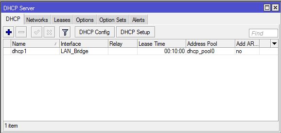
Go to IP > DHCP Server menu item. DHCP Server window will appear.
Click on DHCP Setup button. DHCP Setup window will appear.
Choose bridge interface (LAN_Bridge) from DHCP Server Interface drop down menu and then click Next button.
LAN Block (10.10.70.0/24) will be automatically assigned in DHCP Address Space input field. So, nothing to do. Just click Next button.
LAN Gateway (10.10.70.1) will automatically be assigned in Gateway for DHCP Network input field. So, just click Next button.
IP Pool from where IP address will be assigned to Wireless devices and LAN devices will be automatically assigned from LAN Block (10.10.70.2-10.10.70.254) in Addresses to Give Out input field. So, just click Next button.
Your assigned DNS Server IP will automatically be assigned in DNS Server input filed. So click Next button.
Default DHCP lease time is 10 minute. So, 10 minute will keep assigned in Lease Time input filed. If you want, you can increase lease time as much you want. Click Next button.
Now you will find DHCP Setup successful message window. Just click OK button.
MikroTik DHCP Server Setup
MikroTik WiFi AP with DHCP Server is now ready. Now connect any wireless device or connect any LAN device. The device will get IP address, default gateway and other network parameters automatically and be able to get internet access.
With this MikroTik WiFi AP configuration any wireless user who knows WiFi password can connect with SSID and any LAN user who will be connected with LAN cable can able to get access to DHCP Server and DHCP Server will be happy to provide him/her IP address, default gateway and other network parameters because there is no filter rule to block unauthorized access.
MikroTik Wireless or WiFi AP is smart enough granting access based on MAC address. But MAC address filtering can only save WiFi access. LAN users should also filter based on MAC Address. For this, it is always better to use Static DHCP Server Configuration which will filter access based on MAC Address.
How to Configure MikroTik WiFi AP with DHCP Server in hAP lite Wireless Router has been discussed in this article. I hope you will now be able to configure MikroTik Wireless Router following the above steps properly. However, if you face any confusion to follow the above steps properly, feel free to discuss in comment or contact with me from Contact page. I will try my best to stay with you.
В данной статье мы установим отдельный контейнер LXC, я кратко расскажу чем контейнеры отличаются от обычных виртуальных машин.
Установим и настроим сервис для обработки доменных имен в своей локальной сети BIND9
Настроим роутер(MikroTik) и сеть для того, чтобы наши устройства в локальной сети могли находить наши доменные имена.
И для примера настроим наш PVE1(сам сервер) для доступа к нему по доменному имени, а не IP адресу.
Для чего вообще это делать?
В общих чертах это не обязательно, но намного приятнее обращаться к своим сервисам по привычному доменному имени, а не IP адресу.
Например к медиасервису Plex я обращаюсь по адресу plex.gregory-gost.ru, а не 192.168.88.8:32400/web. Согласитесь удобнее 🙂
Вроде ничего не упустил 🙂 Кому интересно прошу далее под кат!
Текста много, предупреждаю сразу 😉
Установка контейнера LXC в Proxmox-VE
Для того, чтобы наш DNS сервис работал самостоятельно и не зависел от наших попыток, что-то сломать сделать, я его установил в отдельный LXC контейнер(виртуальную среду).
Что такое LXC контейнер?LXC (англ. Linux Containers) — система виртуализации на уровне операционной системы для запуска нескольких изолированных экземпляров операционной системы Linux на одном узле. LXC не использует виртуальные машины, а создаёт виртуальное окружение с собственным пространством процессов и сетевым стеком. Все экземпляры LXC используют один экземпляр ядра операционной системы.
В чем отличие обычной Виртуальной машины от LXC контейнера?
Подробно разбирать не буду, к данной статье это не относится. Просто для справки опишу основное отличие:
Контейнер использует ядро операционной системы сервера. У виртуальной машины может быть совершенно отличное ядро. Для лучшего понимания — в виртуальной машине можно запустить почти все, от Windows, до специфических Linux систем, а в контейнере можно запустить только Linux систему с тем же ядром, Windows уже не запустишь.
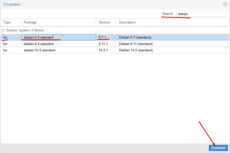
Начнем мы с добавления в наш сервер специального шаблона(Template) операционной системы. В Proxmox их можно скачать из своих репозиториев.
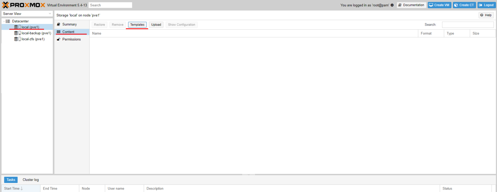
Откроем панель управления через WEB по IP адресу. И перейдем к нашему хранилищу Local(pve1), потом переходим к содержимому(Content) и нажмем кнопку Шаблоны(Templates)
Добавление шаблона
Т.к. наш Proxmox основан на ОС Debian, то я принял для себя решение использовать LXC Debian 9 версии. Мне с ними удобнее работать. Если опыт вам позволяет, то вы можете использовать и другие дистрибутивы, благо выбор позволяет. В 17 версии Proxmox доступен также Alpine, который используют практически во всех Docker контейнерах, как один из самых легковесных.
Находим нужный шаблон и грузим его.
Находим наш шаблон и загружаем его
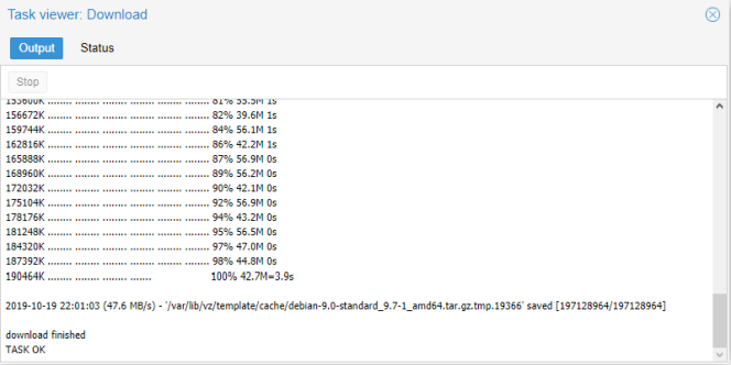
Нам остается только подождать окончания загрузки.
Окончание загрузки
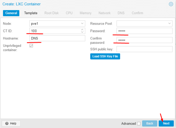
Начинаем установку.
Нажимаем нужную кнопку
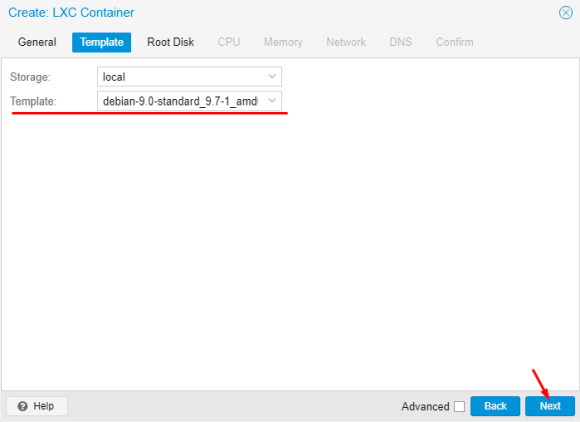
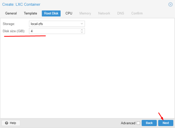
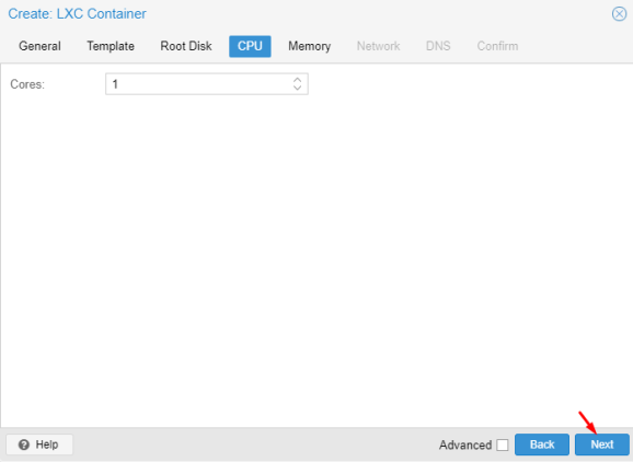
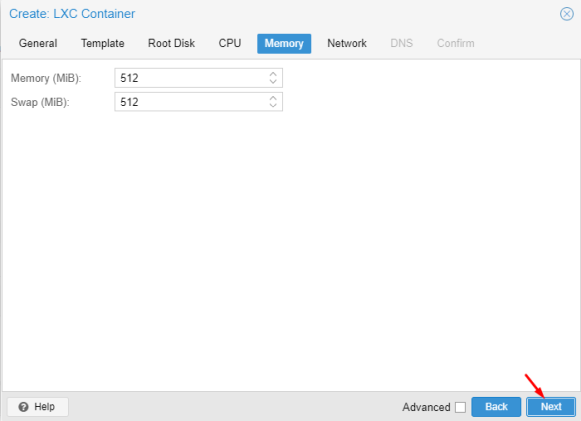
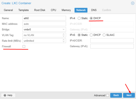
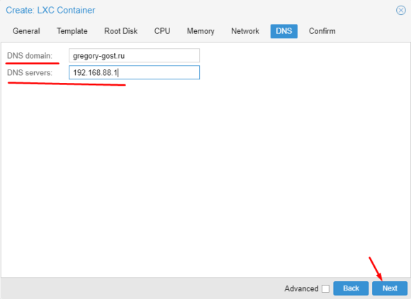
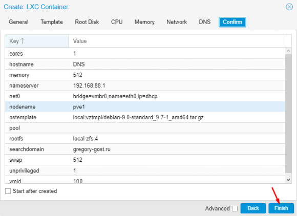
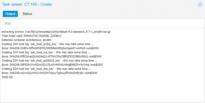
Проводим действия по настройке контейнера
</figur e>
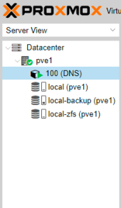
Запускаем контейнер по кнопке Start если еще не сделали это сами 🙂
Запуск контейнера
Все дальнейшие действия будем проводить через консоль:
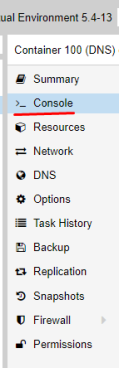
Переходим к консоли контейнера
Далее начинается сам процесс установки и настройки DNS сервиса…
Установка и настройка DNS сервиса BIND9
Обновляем контейнер
apt update && apt full-upgrade -y
Устанавливаем BIND9
apt install bind9 -y
Ждем окончания установки и пока останавливаем сервис
Необходимо сделать так, чтобы локальный DNS сервис корректно обрабатывал локальное доменное имя, а остальные запросы отправлял основному роутеру(шлюзу)
Все файлы настроек и зон в bind9 находятся по пути /etc/bind/
root@DNS:~# ls -l /etc/bind/
total 55
-rw-r--r-- 1 root root 3923 May  3 20:34 bind.keys
-rw-r--r-- 1 root root  237 May  3 20:34 db.0
-rw-r--r-- 1 root root  271 May  3 20:34 db.127
-rw-r--r-- 1 root root  237 May  3 20:34 db.255
-rw-r--r-- 1 root root  353 May  3 20:34 db.empty
-rw-r--r-- 1 root root  270 May  3 20:34 db.local
-rw-r--r-- 1 root root 3171 May  3 20:34 db.root
-rw-r--r-- 1 root bind  463 May  3 20:34 named.conf
-rw-r--r-- 1 root bind  490 May  3 20:34 named.conf.default-zones
-rw-r--r-- 1 root bind  165 May  3 20:34 named.conf.local
-rw-r--r-- 1 root bind  890 Oct 20 17:13 named.conf.options
-rw-r----- 1 bind bind   77 Oct 20 17:13 rndc.key
-rw-r--r-- 1 root root 1317 May  3 20:34 zones.rfc1918
Я решил немного изменить принцип хранения файлов и зон, чтобы было удобнее.
Вот к такому виду необходимо привести конструкцию. Давайте разбираться, что тут и к чему!
root@DNS:~# ls -l /etc/bind/
total 45
drwxr-sr-x 2 root bind    5 Oct 20 20:44 key
-rw-r--r-- 1 root bind  554 Oct 20 20:46 named.conf
-rw-r--r-- 1 root bind 1044 Oct 13 18:32 named.conf.acl
-rw-r--r-- 1 root bind  514 Oct 13 18:33 named.conf.default-zones
-rw-r--r-- 1 root bind  917 Oct 13 18:33 named.conf.local-zones
-rw-r--r-- 1 root bind  891 Oct 13 18:36 named.conf.logging
-rw-r--r-- 1 root bind  397 Oct 13 18:34 named.conf.options
-rw-r--r-- 1 root bind  215 Oct 20 20:45 rndc.conf
drwxr-sr-x 2 root bind   10 Oct 14 20:33 zone
-rw-r--r-- 1 root root 1317 May  3 20:34 zones.rfc1918
Т.к я пока не планирую выводить работу BIND9 на IPv6, то я запустил службу только для IPv4. Для этого необходимо добавить опцию запуска в файл /etc/default/bind9
Добавляем опцию -4 в параметр OPTIONS
# run resolvconf?
RESOLVCONF=no

# startup options for the server
OPTIONS="-u bind -4"
Правим основной файл настроек named.conf:
// Access List
include "/etc/bind/named.conf.acl";

// Options
include "/etc/bind/named.conf.options";

// Key file
include "/etc/bind/key/rndc.key";
include "/etc/bind/key/ns.gregory-gost.ru.key";

// Server
server 192.168.88.7 {
        keys { "ns.gregory-gost.ru"; };
};

// Trusted DNS
acl trusted-dns {
        127.0.0.1;
        key ns.gregory-gost.ru;
};

// Controls Channel
controls {
        inet 127.0.0.1 port 953
        allow { 127.0.0.1; } keys { "rndc-key"; };
};

// Logging
include "/etc/bind/named.conf.logging";

// Zones
include "/etc/bind/named.conf.local-zones";
Описание параметров named.conf
include — подключение отдельных конфигурирующих файлов. Причем порядок не менее важен.server — определяет свойства или поведение, которое этот сервер будет использовать. Например IP адрес и вложенные параметры для него.
server -> keys — определяет какой ключ использовать для подписи при активном DNSSEC
acl trusted-dns — определяет отдельный список доступа и какой ключ использовать для него.
controls — описывает и контролирует доступ к каналу управления, используемому удаленным администратором при использовании утилиты rndc
Создаем отдельный файл named.conf.acl:
Acl (access control list) — позволяет задать именованный список сетей. Формат раздела: acl «имя_сети» {ip; ip; ip; };
У меня пока две разделенные зоны, но с одной подсетью, соответственно разделяю по выделенным диапазонам. Я прописывал все выделенные IP адреса.
directory — указывает абсолютный путь к рабочему каталогу сервера. Все последующие относительные пути используют этот базовый каталог. Если параметры каталога не указаны, используется каталог, из которого был загружен BIND.dnssec-enable — указывает, что используется защищенная служба DNS
dnssec-validation — указывает, что распознаватель(сервер имен с кэшированием или только для кэширования) будет пытаться проверить ответы из включенных(подписанных) зон DNSSEC
dump-file — определяет абсолютный путь, по которому BIND создает дамп базы данных (кеша) в ответ на rndc dumpdb
statistics-file — Этот оператор определяет имя файла, в который будут записываться данные при выдаче команды rndc stats
version — выводить версию сервера или нет при специфических запросах.
port — на каком порту обрабатывать запросы. Лучше не менять, т.к. порт для всех DNS запросов стандартный 53
listen-on — на каких IPv4 ожидать поступления DNS запросов
listen-on-v6 — на каких IPv6 ожидать поступления DNS запросов
allow-transfer — определяет список совпадений, например IP-адрес(а), которому разрешено передавать(копировать) информацию о зоне с сервера(главного или подчиненного для зоны)
allow-query — определяет список совпадений IP-адресов, которым разрешено отправлять запросы на сервер
allow-recursion — определяет список совпадений IP-адресов, которым разрешено отправлять рекурсивные запросы на сервер
Создаем отдельный файл named.conf.logging:
В этом разделе описывается условие ведения журнала.
channel — BIND принимает несколько определений каналов и параметры того, как их вести.category — управляет тем, какие категории заносятся в различные определенные или стандартные имена каналов.
На файле named.conf.local-zones я бы хотел остановится немного подробнее. Именно в данном файле мы определяем направления. Именно в этом файле указываются сами зоны с доменными именами и правила их обработки. Как я уже писал, у меня всего две зоны и именно для двух зон мне необходимо сделать идентичные описания, но с различными параметрами.
Переименуем стандартный файл named.conf.local в named.conf.local-zones
view "lan_zone_one" {

        match-clients {
                loc;
                lan-pool-one;
        };
        allow-query {
                loc;
                lan-pool-one;
        };
        allow-transfer {
                trusted-dns;
        };
        allow-update {
                none;
        };
        recursion yes;
        forwarders {
                192.168.88.1;
        };
        include "/etc/bind/named.conf.default-zones";

        zone "gregory-gost.ru" {
                type master;
                file "/etc/bind/zone/db.gregory-gost.ru";
        };

        zone "88.168.192.in-addr.arpa" {
                type master;
                file "/etc/bind/zone/db.gregory-gost.ru.inverse";
        };

};

view "lan_zone_two" {

        match-clients {
                loc;
                lan-pool-two;
        };
        allow-query {
                loc;
                lan-pool-two;
        };
        allow-transfer {
                trusted-dns;
        };
        allow-update {
                none;
        };
        recursion yes;
        forwarders {
                192.168.88.30;
        };
        include "/etc/bind/named.conf.default-zones";

        zone "gregory-gost.ru" {
                type master;
                file "/etc/bind/zone/db.gregory-gost.ru";
        };

        zone "88.168.192.in-addr.arpa" {
                type master;
                file "/etc/bind/zone/db.gregory-gost.ru.inverse";
        };

};
Описание параметров файла named.conf.local-zones
view — позволяет BIND предоставлять различные функциональные возможности в зависимости от доступа к нему определенных хостов. Т.е. позволяет разделить доменную зону, например для внешних и внутренних запросов. У нас пока только внутренние!match-clients — основной список клиентов(хостов) для совпадений с направлением
allow-query — определяет список совпадений IP-адресов, которым разрешено отправлять запросы на сервер
allow-transfer — определяет список совпадений, например IP-адрес(а), которому разрешено передавать(копировать) информацию о зоне с сервера(главного или подчиненного для зоны)
allow-update — определяет список совпадений, которым разрешено отправлять динамические обновления для мастер-зон
recursion — если для рекурсии установлено значение «да»(по умолчанию), сервер всегда будет обеспечивать рекурсивное поведение запросов, если этого требует клиент(распознаватель).
forwarders — определяет список IP-адресов(адресов) (и необязательных номеров портов), на которые будут перенаправляться запросы. Именно этот параметр отвечает за перенаправление неизвестных запросов к своему роутеру.
zone — тут описываются управляющие свойства и путь к файлу с описанием самих зон
Файл rndc.conf создавать не обязательно, но если вы хотите изменить ключ rndc.key, то можно воспользоваться данным механизмом.
Необходимо подать команду:
rndc-confgen > rndc.conf
Содержимое файла выглядит так:
# Start of rndc.conf
key "rndc-key" {
        algorithm hmac-md5;
        secret "S+vUL+wY/RO5JdNZ6VVX2A==";
};

options {
        default-key "rndc-key";
        default-server 127.0.0.1;
        default-port 953;
};
# End of rndc.conf

# Use with the following in named.conf, adjusting the allow list as needed:
# key "rndc-key" {
#       algorithm hmac-md5;
#       secret "S+vUL+wY/RO5JdNZ6VVX2A==";
# };
#
# controls {
#       inet 127.0.0.1 port 953
#               allow { 127.0.0.1; } keys { "rndc-key"; };
# };
# End of named.conf
Блок key «rndc-key» это и есть содержимое файла ключа rndc.key. Потому вы можете скопировать этот текст в файл rndc.key
С файлами настроек разобрались, теперь необходимо создать нужные папки и переместить туда базовые файлы с описанием зон.
Создаем папки:
Полное описание параметров файлов конфигурации BIND9 можно найти тут: zytrax.com (ENG)
Теперь самое интересное, а именно описание доменных зон!
Описание локальных доменных зон
У нас уже есть базовые доменные зоны и мы указали в файле конфигурации наши локальные зоны. Возможно вы это заметили в файле named.conf.local-zones
Пункты:
        zone "gregory-gost.ru" {
                type master;
                file "/etc/bind/zone/db.gregory-gost.ru";
        };

        zone "88.168.192.in-addr.arpa" {
                type master;
                file "/etc/bind/zone/db.gregory-gost.ru.inverse";
        };
Соответственно нам необходимо создать два файла:
1. /etc/bind/zone/db.gregory-gost.ru
2. /etc/bind/zone/db.gregory-gost.ru.inverse
Эти два файла называются зонами прямого просмотра и зонами обратного просмотра. Почему так? А потому что DNS работает в обе стороны! Вы можете попасть через доменное имя, как на IP адрес так и наоборот, проверить IP адрес на привязку к нему доменного имени.
Представляю вам файл зоны прямого просмотра:
;
; Zone Front view
;
$TTL 3600
@               IN      SOA     gregory-gost.ru.        example.gregory-gost.ru. (
        2019101401      ; Serial
                1d      ; Refresh
                1h      ; Retry
                1w      ; Expire
                2h      ; Negative Cache TTL
)

@               IN      NS      ns1.hostdomen.ru.
@               IN      NS      ns2.hostdomen.ru.
@               IN      NS      ns3.hostdomen.org.
@               IN      NS      ns4.hostdomen.org.
@               IN      A       99.55.99.199
www             IN      CNAME   gregory-gost.ru.

@               IN      NS      ns.gregory-gost.ru.
ns              IN      A       192.168.88.7

pve1            IN      A       192.168.88.6
Описание файла прямого просмотра db.gregory-gost.ru
$TTL — Время активности записей в секундах. Необходим, чтобы указать другим DNS-серверам, как долго стоит хранить запись у себя в кэше. Слишком малое значение увеличит нагрузку на сервер, а большое приведет к слишком длительному процессу изменения записи. Поставим 1 час.SOA-запись — Запись идет сразу после параметра TTL и она хранит общие настройки для зоны.
Запись начинается с символа @ продолжается указателем на тип сети IN(Internet), потом тип SOA, потом идет домен(точка после ru обязательна!), потом идет email адрес без символа @. Символ @ заменяется на точку.(также в конце доменного имени точка после ru обязательна!)
Serial — порядковый номер изменения. Его необходимо каждый раз менять вручную при редактировании файла. С помощью него вторичный сервер (если такой есть), может определить, что были изменения и начать процесс копирования настроек. Имеет формат даты и порядкового номера: 2019101401 -> 2019-10-14 №01 (т.е. версия №01 от 14 октября 2019 г.)
Refresh — указывает вторичным серверам, через какой промежуток времени они должны сделать запрос на обновление зоны.
Retry — говорит вторичным серверам, как часто повторять попытки на обновление зоны, если первичный сервер не смог дать ответ (сервис был недоступен).
Expire — время в секундах, которое может работать вторичный сервер, если недоступен первичный. Если данный период истечет, а вторичный сервер так и не смог обновить зону, он должен прекратить отвечать на запросы.
Далее идут типы записей, кто работал с хостингами и настраивал доменные имена увидят знакомые типы записей.
Основные типы записей, использующиеся в DNS:
A — сопоставляет имени узла соответствующий IP-адрес. Именно его мы и будем использовать!
NS — указатель на DNS-сервера, которые обслуживают данную зону. Тоже используем не много 🙂
MX — почтовая запись. Указывает на почтовые сервера, которые обслуживают домен. Поддерживает приоритезацию при указании нескольких записей, клиент будет ориентироваться на значение той, для которой указано меньшее число.
CNAME — aliase или псевдоним. Перенаправляет запрос на другую запись.
TXT — произвольная запись. Чаще всего используется для настройки средств повышения качества отправки почтовых сообщений.
Ну а сам принцип построения записи вы можете видеть в примере файла.
Как видите после записи доменных имен в этих файлах всегда ставится точка: gregory-gost.ru.
Будьте внимательны!
Остался файл зоны обратного просмотра:
;
; Zones invert view
;
$TTL 3600
@               IN      SOA     gregory-gost.ru.  example.gregory-gost.ru. (
        2019101401      ; Serial
                1d      ; Refresh
                1h      ; Retry
                1w      ; Expire
                2h      ; Negative Cache TTL
)

@               IN      NS      ns1.hostdomen.ru.
@               IN      NS      ns2.hostdomen.ru.
@               IN      NS      ns3.hostdomen.org.
@               IN      NS      ns4.hostdomen.org.

@               IN      NS      ns.gregory-gost.ru.
7               IN      PTR     ns.gregory-gost.ru.

6               IN      PTR     pve1.gregory-gost.ru.
Описание файла прямого просмотра db.gregory-gost.ru
По сути это обратная операция преобразования IP адреса в доменное имя.Адрес преобразуется через строку 88.168.192.in-addr.arpa подстановкой числа описанного в зоне.
Например 6 IN PTR pve1.gregory-gost.ru. — это IP 192.168.88.6
Вы могли видеть еще непонятные доменные имена, по типу ns1.hostdomen.ru. я оставил это для нормальной обработки основного доменного имени т.к. мой домен привязан к хостингу.
Сохраняем все наши файлы и пробуем запустить сервис BIND9
service bind9 start
Для проверки работает или нет, сначала проверяем сервис
service bind9 status
Если видим что-то похожее значит все ок
Active: active (running) since Sun 2019-10-20 20:57:57 UTC; 21h ago
После правки файлов зон, необходимо обнулить кеш и обновить файлы зон:
rndc reload
И не забывайте менять строку Serial при каждом внесении изменений!
Если вы установили пакет dnsutils, вы можете проверить свою установку используя обзорную утилиту DNS dig
После установки BIND9 примените dig к интерфейсу обратной петли (loopback), чтобы убедиться, что порт 53 прослушивается. Из терминала наберите:
dig -x 127.0.0.1
В ответ получите, что-то такое:
root@DNS:~# dig -x 127.0.0.1

; <<>> DiG 9.10.3-P4-Debian <<>> -x 127.0.0.1
;; global options: +cmd
;; Got answer:
;; ->>HEADER<<- opcode: QUERY, status: NOERROR, id: 9723
;; flags: qr aa rd ra; QUERY: 1, ANSWER: 1, AUTHORITY: 1, ADDITIONAL: 3

;; OPT PSEUDOSECTION:
; EDNS: version: 0, flags:; udp: 4096
;; QUESTION SECTION:
;1.0.0.127.in-addr.arpa.                IN      PTR

;; ANSWER SECTION:
1.0.0.127.in-addr.arpa. 604800  IN      PTR     localhost.

;; AUTHORITY SECTION:
127.in-addr.arpa.       604800  IN      NS      localhost.

;; ADDITIONAL SECTION:
localhost.              604800  IN      A       127.0.0.1
localhost.              604800  IN      AAAA    ::1

;; Query time: 1 msec
;; SERVER: 192.168.88.7#53(192.168.88.7)
;; WHEN: Mon Oct 21 18:18:15 UTC 2019
;; MSG SIZE  rcvd: 132
named-checkzone
Хороший способ проверить ваши файлы зон — это использовать утилиту named-checkzone, установленную вместе с пакетом bind9. Эта утилита позволяет вам убедиться в корректности настроек до перезапуска BIND9 и применения изменений.
zone pve1.gregory-gost.ru/IN: loaded serial 2019101401
OK
Очистить кеш данных DNS сервиса можно командой rndc flush
Для нормальной обработки доменных имен обычно необходимо подождать некоторое время, от минуты до десяти минут.
Все хорошо. Займемся настройкой сети, ведь мы хотим, чтобы локальные доменные имена работали на всех наших локальных устройствах (умеющих работать с DNS)
Настройка локальной сети для обработки внутренних DNS запросов
Локальная сеть настраивается достаточно просто.
Вам необходимо указать IP адрес LXC контейнера, как основной DNS сервер. Его будут получать клиенты через DHCP.
Для устройств со статическими IP настройками, необходимо DNS прописать вручную.
Я покажу, как добавить DNS в DHCP сервер, на примере своего роутера MikroTik
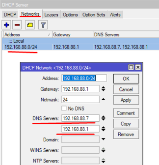
Открываем Winbox или терминал, подключаемся к нашему роутеру и идем по пути: IP -> DHCP Server вкладка Networks
Добавляем IP адрес нашего BIND9 выше IP роутера
Консольно:
[RC]/ip dhcp-server network set dns-server=192.168.88.7,192.168.88.1[/RC]
Далее обновляем аренду для всех клиентов или какого-то одного для проверки.
Например в Windows 10 можно запустить командную строку(cmd) и проверить получение DNS:
Видим строку DNS-серверы. . . . . . . . . . . : 192.168.88.7 значит наш ПК получает DNS корректно.
Но для нормального открытия WEB страницы по доменному имени этого еще не достаточно!
Необходимо, чтобы на целевом IP адресе, WEB интерфейс корректно обработал такой запрос.
Давайте на примере основной хост машины PVE, попробуем получить к ней доступ через указанное нами доменное имя pve1.gregory-gost.ru.
Настройка открытия WEB интерфейса Proxmox-VE по доменному имени
Для того, чтобы запрос к доменному имени был обработан корректно, нам необходимо настроить специальный сервис, который будет за это отвечать.
Этот сервис nginx. Очень мощная штука по которой пишут не маленькие мануалы. Поэтому мы ограничимся самым простым функционалом.
В общем основная суть того, что происходит.
При запросах по доменному имени pve1.gregory-gost.ru мы попадаем на 80 порт(стандартный HTTP) и нас перенаправляет на 443 порт(HTTPS) на котором работает WEB Proxmox-VE.
Ну а там запрос поступает уже на свой внутренний адрес и порт: https://localhost:8006 при этом для нас, все скрыто за кулисами nginx 🙂
По сути, именно таким образом все это и работает.
Открытый WEB через доменное имя
По данному мануалу, локальные доменные имена не доступны из Интернета!
Если вы столкнулись с ошибкой «401 no token»:
Необходимо отредактировать файл запуска сервиса nginx
Статья получилась достаточно большой. Хотя это еще не все, вы могли заметить закомментированные строки связанные с SSL сертификатами.
Возможно позже я разберусь с этим и дополню статью, а пока приходится мириться с паникой браузера в отношении непроверенных сертификатов.
Существуют и системы альтернативные BIND. Например PowerDNS, Unbound, djbdns, Dnsmasq.
Вы можете рассмотреть их для реализации похожего функционала.
Мне остается только напомнить про дальнейшие шаги по реализации своего домашнего сервера:
MikroTik RouterOS does not always include all the packages those are developed by MikroTik team. So, sometimes you may find that some packages are missing in your RouterOS such as NTP package, DUDE package, Wireless package, CAPsMAN package and so on. Specially, user manager package which is totally a separate MikroTik RADIUS package used to manage user authentication, authorization and accounting is always missing. Also upgrading RouterOS or downgrading RouterOS you may find that some packages are missing there. So, if you find package missing in your RouterOS, you must install them manually. But installing these extra packages sometimes may be difficult if don’t know the proper guideline. Some of our loyal readers also told me that they are facing problem to install these extra packages specially user manager package. So, in this article I will discuss how to install MikroTik extra packages properly with step by step guideline.
How to Install MikroTik Packages
If you don’t know the proper guideline, you may spend hours to hours to install RouterOS extra packages but your result will be null. So, I am sharing here how to install MikroTik extra packages with proper guideline.
Extra packages in MikroTik can properly be installed with the following four steps.
Finding Architecture Name and RouterOS version
Downloading Exact Packages with Architecture Name and Version
Uploading Downloaded Packages to MikroTik Root Directory
Rebooting Router to Install Uploaded Packages
Step 1: Finding Architecture Name and RouterOS Version
It is important to know the Architecture Name and the current RouterOS Version before going to download extra packages. The following steps will show how to find the architecture name and the current RouterOS version.
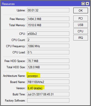
From Winbox, go to System > Resources menu item. Resources window will appear.
Architecture Name and RouterOS version will be found in Resources window.
Finding Architecture Name and Version
From the above Resource window we can see that the Architecture Name of this MikroTik Router is powerpc RouterOS version is 6.40 (stable).
Step 2: Downloading Exact Packages with Architecture Name and Version
Knowing Architecture Name and RouterOS version, we will now download packages from MikroTik Download Archive. The following steps will show how to choose accurate RouterOS version for your MikroTik Router.
Go to MikroTik Download Page and select your current RouterOS version. You will find a list of RouterOS version for all Router Board architectures.
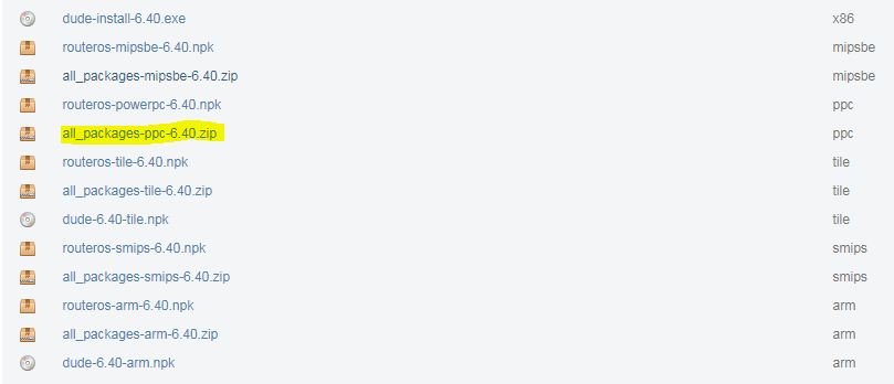
Click on the ZIP (.zip) file that will match with your Architecture Name. The file format will be all_packages-architecture_name-routeros_version.zip.
Your download will be started and within few minutes it will be finished.
Downloading Packages from MikroTik Download Archive
From the above image we can see that the ZIP file for powerpc is all_packages-ppc-6.40.zip.
Step 3: Uploading Downloaded File to MikroTik Root Directory
After downloading exact ZIP file for MikroTik RouterOS, we will now extract this zip file and upload desired package files to MikroTik root directory. The following steps will show how to upload downloaded package file to MikroTik root directory.
Extract your downloaded ZIP file. You will find your desired package files (.npk) in your extracted folder. The file format will be package_name-routeros_version-architecture_name.npk.
From Winbox, click on Files menu item. File List window will appear.
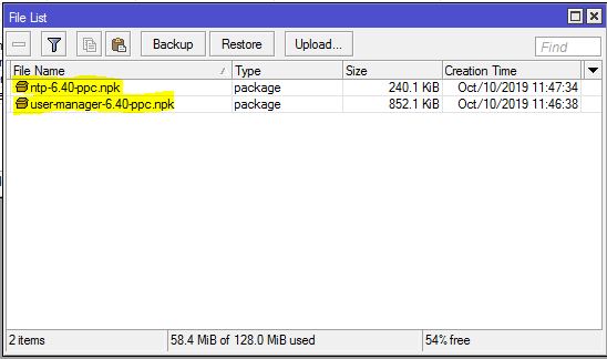
Now drag and drop your desired package files (NPK file) to this File List window.
Installing User Manager and NTP Packages
From the above image we can see that User Manage and NTP packages are uploaded to install in RouterOS.
Step 4: Rebooting Router to Install Uploaded Packages
We are now ready to install our missing packages in RouterOS. We will now provide reboot command to install these packages.
From Winbox, go to System > Reboot menu item.
It will ask to confirm reboot. Click on Yes button.
Your Router will be rebooted and after reboot you will find that your desired packages will be installed and no file will remain in File List window.
To check whether your packages are installed or not, go to System > Packages menu item. Now you will find that your installed packages will be listed in Package List window.
If you face any confusion to follow the above steps properly, watch the following video on Installing extra packages in MikroTik Router. I hope it will reduces your any confusion.
How to install extra packages in MikroTik Router properly has been discussed in this article. I hope you will now be able to install your missing RouterOS packages if required. However, if you face any confusion to install extra packages, feel free to discuss in comment or contact with me from Contact page. I will try my best to stay with you.