Сегодня команда Itsecforu хочет познакомить и посоветовать Вам сайт посвященный обучению в области ИТ – http://курсы-по-ит.рф .
Создателем является Дмитрий Скоромнов, имеющий богатый опыт в области сетевых технологий и системного администрирования, а также огромное количество сертификатов (в том числе и международных) от различных вендоров.
Онлайн курсы разделены на два основных раздела:
1. Университет MikroTik. Вы сможете научится работать с этим оборудованием
2. Школа системного администратора.
Обучение состоит из просмотра видео, работы с конспектом курса, прохождения контрольных вопросов, а также с возможностью обратной связи с куратором, прохождения экзамена и получения сертификата, подтверждающего обучение.
Стоит отметить символическую стоимость, которую автор просит за обучение с последующей выдачей сертификата, например для курса “Основы сетевых технологий” – она составляет всего 490 р. Сам курс написан очень здорово – простым языком, с доступными примерами. В течение курса автор постоянно возвращается к уже пройденному материалу, что позволяет закрепить полученные знания, а также умело расставляет акценты на тех вещах которые необходимо подчеркнуть слушателям в первую очередь!
Желаем успехов Дмитрию в создании новых интересных программ обучения, а читателям советуем обратить внимание на вышеуказанный ресурс:
На днях менял в офисе шлюз freebsd на mikrotik. Сразу скажу зачем это делал, чтобы не было вопросов. Freebsd была очень старая, обслуживать или что-то настраивать на ней было неудобно, пришло время ее заменить. Перенес все настройки, в том числе и проброс портов со старого шлюза на новый. В сети стоял астериск за nat и с одним номером возникли проблемы.
Эта настройка нужна для того, чтобы сервер (например почтовый) опубликованный в Интернете, был доступен по внешнему адресу внутри сети за NAT-ом.
А как настроить, достаточно инфы в сети.
Load balancing and link redundancy is the main concern to any network administrator. Because, they always want to keep live their network 24/7. If you have multiple WAN connections, you can easily make a load balancing as well as link redundancy network with MikroTik Router. Different types of load balancing and link redundancy are present in MikroTik Router. ECMP Load Balancing is one of them. ECMP is so easy to implement and it provides an perfect load balancing solution. In this article, I am going to show how to configure a DUAL WAN Load Balancing network with Failover using ECMP method in Mikrotik Router.
ECMP (Equal Cost Multi Path)Routing
ECMP stands for Equal-Cost Multi-Path routing. ECMP is persistent per-connection load balancing or per-src-dst-address combination load balancing where a new gateway is chosen for each source and destination IP pair. It means that, for example, one FTP connection will use only one link, but new connection to a different server will use another link.
Network Diagram We will configure Dual WAN load balancing over two equal gateways using ECMP method according to the following diagram.
Load Balancing and Link Redundancy Network
In this network, there are two ISP connections (ISP1 and ISP2) which are connected to ether1 and ether2 port of the MikroTik Router. A number of network devices are connected to the MikroTik router through a network switch. The uplink port of the LAN switch is connected to the Router’s ether10 port and using as the LAN network of the router. We will configure DUAL WAN ECMP load balancing in this MikroTik Router so that LAN traffic can pass through both WAN links equally.
This ECMP configuration will also ensure Link Redundancy. So, if any ISP connection gets disconnected, LAN traffic will pass through the available ISP connection until the lost ISP connection gets available.
ECMP Load Balancing and Link Redundancy Configuration
Complete ECMP configuration for a load balancing and link redundancy network according to the above network diagram can be divided into 4 steps.
Assigning WAN and LAN IP Addresses
DNS Configuration
NAT Configuration
ECMP Route Configuration
Step 1: Assigning WAN and LAN IP Addresses
At first we will assign WAN and LAN IP in MikroTik Router. For this article configuration, I am using the following two WAN IP addresses and their respected gateway addresses.
WAN1 IP Address: 172.22.15.221/24 and Gateway:172.22.15.1
WAN2 IP Address: 192.168.168.210/24 and Gateway:192.168.168.254
I am using these WAN IP and Gateway addresses for the configuration of this article as well as the video tutorial that I will upload in my channel but in practical your WAN IP addresses and Gateway addresses must be different and these will be provided by your ISP Company. For this article configuration, I am also using the following LAN IP block and Gateway.
IP Block: 192.168.10.0/24
Gateway: 192.168.10.254
Now we will assign the above WAN and LAN IP addresses on MikroTik Interfaces. The following steps will show how to assign IP address on MikroTik Interfaces.
Login to your MikroTik router using Winbox software with full permission user privilege.
Go to
Click on PLUS SIGN (+). New Address window will appear. Put your WAN1 IP address (in this article: 172.22.15.221/24) in Address input box and choose WAN1 interface (in this article: ether1) from Interface drop-down menu and then click Apply and OK
Similarly, click on PLUS SIGN (+) and put WAN2 IP address (in this article: 192.168.168.210/24) in Address input field and choose WAN2 interface (in this article: ether2) from Interface drop-down menu and then click Apply and OK button.
Click on PLUS SIGN (+) again and put LAN gateway IP (in this article: 192.168.10.254/24) in Address input field and choose LAN interface (in this article: ether10) from Interface drop-down menu and then click Apply and OK button.
Step 2: DNS Server Configuration
DNS is not a mandatory configuration in MikroTik Router but it is necessary for a complete MikroTik Router configuration. Optionally, you can turn your MikroTik router into a DNS Server which will be beneficial for your network. So, if you want to set DNS IP for your MikroTik router as well as want to turn your MikroTik router into a DNS server, follow the below simple steps.
Go to IP > DNS menu item. DNS Settings window will appear. Put DNS server IP that is provided to you by your ISP or use public DNS server IP 8.8.8.8 in Servers input field.
Optionally, you can click on Allow Remote Requests checkbox to turn MikroTik Router into a DNS Server. But you have to block DNS requests from outside of your LAN otherwise your MikroTik will be used as a DNS server by the public users if they know your MikroTik’s public IP. Follow my article about MikroTik router basic configuration that will show you steps to block DNS requests from public network.
Now click Apply and OK button.
Step 3: NAT Configuration
We will now create two masquerade NAT rules in MikroTik Router so that LAN users can access internet through the both ISP connections. That means, if any packet leaves via ether1, it will be NATed to ISP1 gateway IP address and if any packet leaves via ether2, it will be NATed to ISP2 gateway IP address. The following steps will show how to create masquerade NAT rule in MikroTik Router.
Go to IP > Firewall menu option. Firewall window will appear.
Click on NAT tab and then click on PLUS SIGN (+). New NAT Rule window will appear now. From General tab, choose srcnat from Chain drop-down menu and choose ISP1 interface (in this article: ether1) from Out. Interface drop-down menu. Now click on Action tab and choose masquerade from Action drop-down menu and then click Apply and OK button.
Similarly, click on PLUS SIGN (+) again and choose srcnat from Chain drop-down menu and choose your ISP2 interface (in this article: ether2) from Out. Interface drop-down menu. Now click on Action tab and choose masquerade from Action drop-down menu and then click Apply and OK button.
Step 4: Routing Configuration
We will now configure ECMP (Equal Cost Multi-Path) gateway over two WAN links. The following steps will show how to assign ECMP gateway in MikroTik Router.
Go to IP > Routes menu option. Route List window will appear.
Click on PLUS SIGN (+). New Route window will appear.
Put ISP1 gateway IP (in this article: 172.22.15.221) in Gateway input box and then click on Add new value button located after gateway input box. New gateway input box will appear. Put WAN2 gateway IP (in this article: 192.168.168.254) in new Gateway input box.
Now choose ping from Check Gateway drop-down menu.
Click Apply and OK button.
ECMP configuration that we have done in the above steps will send network traffics through the both ISP connections equally. That means, one connection among every two connections will be sent through ISP1 connection and another connection will be sent through ISP2 connection. So, you should have equal bandwidth connection from both ISP Company. Otherwise, your bandwidth will be wasted. But if you have unequal bandwidth connection from these two ISP Company, how do you reduce your bandwidth waste? For this follow my another article on unequal DUAL WAN Load Balancing with Failover using ECMP.
Connections to the Router Itself
With all multi-gateway situations there is a usual problem to reach router from public network via one, other or both gateways. Because outgoing packets use same routing decision as packets those are going through the router. So reply to a packet that was received via WAN1 might be sending out via WAN2. To avoid this we need to do policy based routing. The following steps will show how to mark router’s incoming connection to pass it over proper gateway.
Go to IP > Firewall menu option and click on Mangle tab. Now click on PLUS SIGN (+). New Mangle Rule window will appear now.
From General tab, choose input from Chain drop-down menu and choose ISP1 interface (in this article: ether1) from In. Interface drop-down menu. Now click on Action tab and choose mark connection from Action drop-down menu and put connection name (isp1_conn) whatever string you like in New Connection Mark input field and then uncheck the Passthrough check box if it is checked. Click Apply and OK button.
Similarly, click on PLUS SIGN (+) and choose input from Chain drop-down menu and then choose ISP2 interface (in this article: ether2) from In. Interface drop-down menu. Click on Action tab and choose mark connection from Action drop-down menu and put connection name (isp2_conn) whatever string you like in New Connection Mark input field and uncheck the Passthrough checkbox if it is checked and then click Apply and OK button.
Now click on PLUS SIGN (+) and choose output from Chain drop-down menu and then click on Connection Mark drop-down menu and choose ISP1 connection mark (in this article: isp1_conn ) that you have created at the first step. Now click on Action tab and choose mark routing from Action drop-down menu and put routing mark name (to_isp1) in New Routing Mark input field and uncheck the Passthrough checkbox if it is checked and then click Apply and OK button.
Similarly, click on PLUS SIGN (+). Choose output from Chain drop-down menu and choose ISP2 connection mark (in this article: isp2_conn) that you have created at the second step. Now click on Action tab and choose mark routing from Action drop-down menu and then put routing mark name (to_isp2) in New Routing Mark input box and uncheck the Passthrough checkbox if it is checked. Click Apply and OK button.
We have created policy to pass router’s incoming packets to the respected WAN interface. Now we will create routing based on this policy.
Go to IP > Routes menu option. Route List window will appear.
Click on PLUS SIGN (+) and put ISP1 gateway IP (172.22.15.221) in Gateway input box and then choose ISP1 routing mark (in this article: to_isp1) from Routing Mark drop-down menu. Click Apply and OK button.
Similarly, click on PLUS SIGN (+) and put ISP2 gateway IP (192.168.168.254) in Gateway input box and choose ISP2 routing mark (in this article: to_isp2) from Routing Mark drop-down menu. Now click Apply and OK button.
Policy based routing to get router properly from public network has been completed. Now ECMP load balancing will affect no more on getting router from public network.
If you follow the above 4 steps, you can easily configure a load balancing and link redundancy network in your MikroTik Router. However, if you face any confusion to do the above 4 steps successfully, watch the following video tutorial about MikroTik ECMP load balancing and link redundancy. I hope, it will show you the proper guide to configure a load balancing and link redundancy network in MikroTik router with ECMP method.
How to Configure MikroTik ECMP load balancing and link redundancy has been discussed in this article. I hope, you will now be able to make a load balancing and failover network with MikroTik Router sucessfully. However, if you face any problem to configure a load balancing and link redundancy network with your MikroTik Router, feel free to discuss in comment or contact with me from Contact page. I will try my best to stay with you.
Load Balancing is a technique used to send network traffic over multiple gateways. If you have multiple ISP connections in your network, you can send your network traffic through those ISP connections and can make a load balancing network. Accidently you may ask me, why will I use multiple ISP connections? What are the benefits to use multiple ISP connections in my network? I will say, ask yourself deeply then you will find the reasons why multiple ISP connections is necessary in your network. However, I am giving you some reasons which will show you the necessities of multiple ISP connections in your network.
No ISP can give you 100% guarantee that their connection will remain always alive. So, it will be better to use more than one ISP connection in your network so that you can increase your internet access probability.
You have an ISP connection that is not so good but you cannot disconnect it because you are using other services (such as Mail, IPPBX etc.) of this ISP. In this case, you can use another ISP which will provide you better service.
You have an ISP connection that is better but high paid bandwidth. In this case, you can purchase another ISP bandwidth which is cheap but their connection is good, not better.
I think, you are now determined to use multiple ISP connections in your network. If you have multiple ISP connections, you can balance your network load as well as you can make link redundancy. There are a number of ways by which you can make load balancing as well as link redundancy using MikroTik router. Among them, today I will show you how to do only load balancing network using Policy Based Routing (PBR) in MikroTik router.
Policy Routing Based on Client IP Address
Policy Based Routing (PBR) is a technique which is used to make routing decisions based on policies those are set by any network administrator. So, today I will show you a policy in MikroTik router by which you can build a load balancing network.
If you have a number of hosts as well as multiple ISP connections, you may group your hosts by IP addresses and then depending on the source IP address send traffic out through different ISP connections. For example, consider a simple office network diagram like below where two ISP connections are being used as gateways of a MikroTik router.
Load Balancing Network over Multiple Gateways
In this network diagram, there are two ISP connections those are being used as WAN connections of a MikroTik router. Also, a number of hosts are connected to this MikroTik router through a distribution switch. As dual WAN connections are available for this MikroTik router, we will create a policy routing so that our half of the total LAN users will access internet through WAN1 ISP connection and rest of the LAN users will access internet through WAN2 ISP connection.
5 Steps to Create Policy Based Routing in MikroTik Router
As like the above simple office network diagram, I hope, you have dual WAN connections in your MikroTik router as well as a number of hosts are connected to this MikroTik router to access internet. Now I will show you how to create routing policy in your MikroTik router so that half of your LAN users will get internet through WAN1 connection and another half of your LAN users will get internet through WAN2 connections. That means, how you can make a load balancing network over these two gateways.
The whole configuration to apply policy based routing for making a load balancing network with MikroTik router can be divided into 5 steps.
Assigning WAN and LAN IP addresses.
DNS Server Configuration
NAT Configuration
Mangle Rule Creation
Route Configuration
Now I will explain all the above steps in my rest of this article for configuring a load balancing network over multiple gateways.
Step 1. Assigning WAN and LAN IP Addresses
For configuring a perfect load balancing network with policy based routing, first you have to assign WAN and LAN IP addresses in your MikroTik Router. As you have two ISP connections, you must have two WAN IP addresses as well as two gateway addresses. For the configuration of this article, I am using below two WAN IP addresses and two gateway addresses for different ISP connections.
WAN1 IP Address:22.15.221/24 and Gateway: 172.22.15.1
WAN2 IP Address:168.168.210/24 and Gateway: 192.168.168.254
I am using these WAN IP addresses and Gateway addresses for the configuration of this article as well as my video tutorial that I have uploaded in my channel, but in practical your WAN IP addresses and Gateway addresses must be different and these will be provided by your ISP Company. However, you also have a LAN network with a large number of hosts. For the configuration of this article, I am assuming the LAN IP block and gateway address will be like below.
IP Block:168.10.0/24
Gateway:168.10.254
We have got our WAN IP addresses and LAN IP block. Now I will show you how to assign these WAN IP addresses and LAN gateway address in your MikroTik router. Follow my bellow steps to assign WAN and LAN IP addresses in your MikroTik router.
Login to your MikroTik router with Winbox software. If you don’t have Winbox software in your collection, download Winbox from this site and then login to your MikroTik with username and password. If you are new in this article as well as in MikroTik router, follow my article about MikroTik router basic configuration which will show you the proper steps to configure a MikroTik router from very beginning.
Go to IP > Addresses menu item from the winbox menu bar. Address List window will appear.
Now click on add new button (PLUS Sign). New Address window will appear. Put your WAN1 IP address (in this article: 172.22.15.221/24) in Address input box and choose WAN1 interface (in this article: ether1) from Interface drop-down menu and then click Apply and OK button.
Similarly, click on add new button again and put your WAN2 IP address (in this article: 192.168.168.210/24) in Address input field and choose WAN2 interface (in this article: ether2) from Interface drop-down menu and then click Apply and OK button.
Again, click on add new button and put your LAN gateway IP (in this article: 192.168.10.254/24) in Address input field and choose your LAN interface (in this article: ether10) from Interface drop-down menu and then click Apply and OK button.
Assigning WAN and LAN IP addresses has been completed. Now we will configure DNS server in our next step.
Step 2. DNS Server Configuration
DNS is not a mandatory configuration in MikroTik router but it is necessary for a complete MikroTik router configuration. Optionally, you can turn your MikroTik router into a DNS server which will be beneficial for your network. So, if you want to set DNS IP in your MikroTik router as well as want to turn your MikroTik into a DNS server, follow my below simple steps.
Go to IP > DNS menu option.DNS Settings window will appear. Put your DNS server IP that is provided to you by your ISP or you can use Google public DNS server IP 8.8.8.8 in Servers input field.
Optionally, you can click on Allow Remote Requests checkbox to turn your MikroTik router into a DNS server. But you have to block DNS requests from outside of your LAN otherwise your MikroTik will be used as a DNS server by the public users if they know your MikroTik public IP. Follow my article about MikroTik router basic configuration which will show you how to block DNS requests from public network.
Now click Apply and OK button.
Our DNS configuration in MikroTik router has been completed. Now we will create masquerade NAT rule so that our LAN user can access internet through our MikroTik router.
Step 3. NAT Configuration
Now we will create a masquerade NAT rule so that our LAN IP can be NATed by MikroTik router. If we don’t create this rule, our LAN users cannot access internet through our MikroTik router. So, follow my bellow steps to create NAT rule in MikroTik router.
Go to IP > Firewall Firewall window will appear. Click on NAT tab in this window and then click on add new button (PLUS Sign). New NAT Rule window will appear.
Under General tab, choose srcnat from Chain drop-down menu and put your LAN IP block address (in this article: 192.168.10.0/24) in Address input field. Now click on Action tab and choose masquerade from Action drop-down menu and then click Apply and OK button.
NAT rule configuration in MikroTik router has been completed. Now we will create Mangle rules in our MikroTik router so that our LAN user can be divided into two groups.
Step 4. Mangle Rule Creation
As we want to send our LAN users through two ISP connections for load balancing, we have to create Mangle rules which will divide our LAN users into two groups and mark them for proper routing. In this article, I am using a class C IP block which is 192.168.10.0/24 for our LAN users. This IP block can be divided into two groups by subnetting like below.
Group A:168.10.0/25
Group B:168.10.128/25
By doing this subnetting, our total users are now divided into two groups. The users who will use IP address between 192.168.10.1 to 192.168.10.126 will have in group A and those who will use IP address between 192.168.10.129 to 192.168.10.253 will have in group B. Now, I will show you two Mangle rules in MikroTik router those will do proper grouping and marking our LAN IP. Follow below steps to create these Mangle rules.
Go to IP > Firewall menu and click on Mangle tab in Firewall window and then click on add new button (PLUS Sign). New Mangle Rule window will appear now.
Choose prerouting option from Chain drop-down menu and put Group A IP block (in this article: 192.168.10.0/25) in Address input field. Click on Action tab and choose mark routing option from Action drop-down menu and put group name (here, GroupA) in New Routing Mark input box and uncheck the Passthrough option and then click Apply and OK button.
Similarly, click on add new button again and choose prerouting option from Chain drop-down menu and put Group B IP block (here, 192.168.10.128/25) in Address input field. Now click on Action tab and choose mark routing option from Action drop-down menu and put group name (here, GroupB) in New Routing Mark input field and uncheck the Passthrough option and then click Apply and OK button.
We have successfully created Mangle rules for grouping our LAN users. Now we will configure routes in MikroTik router so that different groups can access internet through different ISP connection.
Step 5. Route Configuration
After creating Mangle rules, now you have to configure routing so that your different user group can use different WAN connection for accessing internet. So, follow my bellow steps to configure your MikroTik routing properly.
Go to IP > Routes menu option. Route List window will appear now. Click on add new button (PLUS Sign) from this window. New Route window will appear.
Put ISP1 gateway address (here, 172.22.15.1) in Gateway input field and choose your routing mark (here, GroupA) for this gateway from Routing Mark drop-down menu and then click Apply and OK button.
Similarly, click on add new button (+) and put ISP2 gateway address (here, 192.168.168.254) in Gateway input field and choose your routing mark (here, GroupB) for this gateway from Routing Mark drop-down menu and then click Apply and OK button.
Again, click on add new button (+) and put any ISP gateway (here, 172.22.15.1) and Apply and OK button. If you don’t apply this route, your MikroTik cannot access internet.
After this configuration, your GroupA users will access internet through ISP1 gateway and GroupB users will access internet through ISP2 gateway. So, you will get a perfect load balancing network with this configuration. A question may arise in your mind now. Hey bro, what will happen if any ISP connection goes down? Yeah bro, half of your users will be disconnected from internet. As I said before, this configuration is just for load balancing but not for redundancy. I will show in my next article how to do load balancing as well as link redundancy with ECMP in MikroTik router. But if you do the above load balancing configuration for your network, you have to disable Mangle rules as well as routing rules manually if any ISP link goes down suddenly and create a new route rule for passing all users through the active ISP gateway. If you face any problem to create a single route gateway, follow my article about MikroTik router basic configuration which will guide you how to configure a single route for your network.
Proper steps to make a load balancing network in MikroTik router with policy based routing has been show step by step. If you face any problem to do above steps, watch my below video tutorial about MikroTik Load Balancing over Multiple Gateways which will help you to make a load balancing network in MikroTik router properly.
Policy based routing described in this article will provide only Load Balancing solution but Link Redundancy or failover will not be ensured here. If you want to get Load Balancing and Link Redundancy network, you can use MikroTik ECMP Load Balancing and Link Redundancy method. ECMP method is easy to configure but in large network ECMP method has some known issues. On the other hand, MikroTik PCC Load Balancing and Link Redundancy method provides 100% reliable Load Balancing with failover network but configuration is a little bit complex. MikroTik Dual WAN Load Balancing with Fialover using PCC article has described how to easily configure Load Balancing and Link Redundancy network in your MikroTik Router using PCC method.
MikroTik load balancing over multiple gateways has been shown step by step in this article. I hope, you are now able to configure a load balancing network using PBR if you have two ISP connections available. However, if you face any problem to configure a load balancing network with PBR, feel free to discuss in comment or contact with me from Contact page. I will try my best to stay with you.
PPPoE (Point to Point Protocol over Ethernet) is one of the most popular services in MikroTik Router. PPPoE is an extension of the standard Point to Point Protocol (PPP). The difference between them is expressed in transport method: PPPoE employs Ethernet instead of serial modem connection. PPPoE is a client-server protocol that means PPPoE client (IP devices such as Desktop, Laptop, wireless Router etc.) will request for IP information to PPPoE server providing security information (username and password) and PPPoE server will provide IP information by matching that security information.
PPPoE provides extensive user management, network management and accounting benefits to ISPs and network administrators. PPPoE is used mainly by ISPs to control client connections for xDSL and cable modems as well as plain Ethernet networks. PPPoE is now most popularly used in local ISP company because local ISP user can so easily be maintained with this service. So, this article is designed to show how to maintain ISP clients by configuring a PPPoE server in MikroTik Router.
ISP Setup with PPPoE Configuration
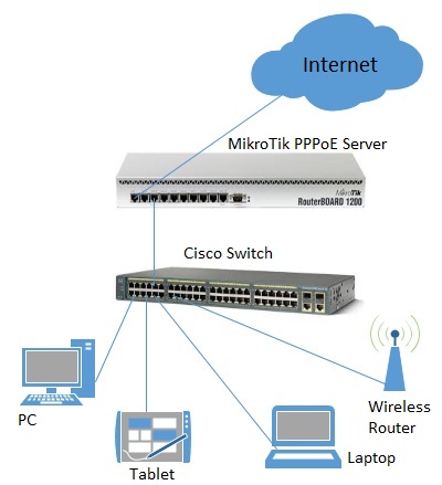
As a system administrator of an ISP company, you have to maintain various offered bandwidth packages such as 512kbps connection, 1Mbps connection, 2Mbps connection and so on. The users of these packages can so easily maintain with MikroTik PPPoE service. Now I’ll show you how to configure a PPPoE service in MikroTik router to maintain your various offered packages. But before starting configuration, I’ll show you a basic simple network diagram where a MikroTik router is serving as a PPPoE server.
PPPoE Network Diagram
In the above network diagram, MikroTik router WAN port (ether 1) is connected to internet and LAN port (ether 2, where we’ll configure PPPoE server) is connected to a distribution switch. PPPoE clients (PC, Laptop, Tablet and Wireless Router) are connected to the PPPoE server through this distribution switch. This is a basic and small network. In practical, your network will be an enterprise network where there may have thousands of clients. But the configuration will be almost same. Only the difference is that you might use multiple Ethernet ports for network simplicity, where we are using only one port here. You might use multiple WAN ports for handling load balancing or network redundancy where we are using only one WAN port here. I’ll discuss load balancing or network redundancy in my coming article. If you want to use multiple Ethernet ports for your LAN, you have to create MikroTik Bridge virtual interface for accumulating multiple interfaces into a single interface and then configure PPPoE server in that virtual interface.
As PPPoE is a client-server protocol, there are two end configurations for PPPoE service.
PPPoE server configuration in MikroTik Router
PPPoE client configuration
To run a PPPoE service in your network, first you have to configure PPPoE server in MikroTik router and then you have to learn how to configure various PPPoE clients. In the rest of this article I’ll show you how to configure PPPoE server in MikroTik router and how to configure PPPoE client in windows operating system. However, I’ll recommend you that search in Google and learn how to configure PPPoE client in various operating platform.
5 Steps to Configure PPPoE Server in MikroTik Router
Now we are going to configure PPPoE server in MikroTik to maintain the clients of a Local ISP. Generally any ISP company has various offered packages depending on bandwidth. It is always better to maintain client bandwidth with MikroTik Queues service although bandwidth can also be maintained with PPPoE service. Specially I‘ll recommend you to use MikroTik PCQ service which I have explained in my previous article about ISP bandwidth management with MikroTik PCQ to maintain your different bandwidth packages. Now we’ll use PPPoE server only for assigning different IP Block’s IP to different clients according to their bandwidth packages. For example, our proposed IP blocks for different bandwidth packages will be like below.
512kbps client will get 172.16.0.0/24 block IP
1Mbps client will get 172.16.1.0/24 block IP
2Mbps client will get 172.16.2.0/24 block IP
So, now we will configure our PPPoE server like that when a user purchase 512kbps connection, he/she will get a 172.16.0.0/24 block IP with his username and password. Similarly, when a user will purchase 1Mbps connection, he/she will get a 172.16.1.0/24 block IP and a 2Mbps user will get a 172.16.2.0/24 block IP. Complete PPPoE server configuration in MikroTik router can be divided into 5 steps.
MikroTik router basic configuration
IP Pool configuration
PPPoE server configuration
PPP profile configuration
PPP secrets (username and password) configuration
Step 1. MikroTik Router Basic Configuration
MikroTik router basic configuration is the prerequisite to complete PPPoE server configuration. MikroTik router basic configuration includes assigning WAN and LAN IP addresses, Gateway configuration, DNS configuration and NAT configuration. If you are a new MikroTik user, feel free to spend some time to study my previous article about MikroTik router basic configuration using Winbox because how to configure MikroTik router from very beginning has been explained in that article. In this article, I assume that you have some knowledge about MikroTik router. So, if you are familiar with MikroTik router, follow below steps to complete MikroTik router basic configuration.
Login to your MikroTik router using winbox software and go to IP > Addresses and then click on add new button (PLUS Sign). New Address window will appear now.
In this window, put your WAN address that you have got from ISP company in Address field and choose ether1 or your WAN interface that like from Interface drop-down menu and then click Apply and OK button. WAN address will be assigned successfully.
Again, click on add new button (PLUS Sign) and put your LAN address (in this article, I am using 172.16.0.1/24) in Address field and then choose your LAN interface from Interface drop-down menu. Now click Apply and OK button. LAN address will be assigned successfully.
Now go to IP > DNS menu. DNS Settings window will appear. In this window, put DNS server address that you have got from ISP company or you can use Google’s public DNS IP (8.8.8.8) in Servers input box. You can put secondary DNS server IP by clicking add new value button located after the Servers input box. Optionally, you can turn your MikroTik router as a DNS server. Turning your MikroTik router as a DNS server is a better idea, I think. Because if you use public DNS server in your network, every DNS request of your user will consume your paid bandwidth. But if you turn MikroTik router as a DNS sever, your user will get DNS solution from MikroTik router without consuming your paid bandwidth. So, if you want to turn MikroTik as a DNS server, click the Allow Remote Requests check box and click Apply and OK button. Your MikroTik router is now a DNS server. All MikroTik IP addresses can now be used as a DNS server IP including WAN IP which is a public IP and problem will arise here. If anyone outside of your LAN use your WAN IP as a DNS IP, your MikroTik will be happy by serving him/her DNS solution consuming your paid bandwidth. So, for stopping DNS request from outside of your LAN, you should apply a firewall rule that will drop all DNS requests coming from your WAN interface (in this article, ether1). For this, go to IP > Firewall menu and click on add new button (PLUS Sign). New Firewall Rule window will appear now. Under General tab, choose Chain: input, Protocol: udp, Dst. Port: 53 and In. Interface: ether1. Now choose Action: drop from Action Tab and click Apply and OK button. Create another similar rule for TCP connection. Click on add new button (PLUS Sign) again and choose Chain: input, Protocol: tcp, Dst.Port: 53 and In. Interface: ether1 and then choose Action: drop under Action tab and click Apply and OK button. Now your MikroTik DNS server is safe from outside of your LAN.
Go to IP > Routes menu for setting Gateway. From Route list window, click on add new button (PLUS). New Route window will appear now. Put your gateway address that you have got from your ISP in Gateway input field and click Apply and OK button. MikroTik default gateway will be assigned now.
Now you have to create NAT rule so that your LAN user can access internet through your router. For this, go to IP > Firewall menu and click on NAT tab. Now click on add new button (PLUS Sign). New NAT Rule window will appear. Choose Chain: srcnat and Address: 172.16.0.0/16 under General tab and choose Action: masquerade from Action tab and then click Apply and OK button. Note that we are using all Class B IP blocks for masquerading because all our LAN IP block will be within this block.
MikroTik router basic configuration for configuring a PPPoE server will be completed if you follow the above steps carefully. If you face any problem to complete MikroTik router basic configuration, follow my video tutorial about MikroTik Router Basic Configuration using Winbox. I hope, it will reduce your confusion. Now we will do our second step about IP Pool configuration for configuring a PPPoE server successfully.
Step 2. IP Pool Configuration
We will now create three IP Pools because we assume that we have three offered packages and our user will get different IP block IP according to their package purchase. So, follow below steps to create IP Pools in your MikroTik router.
Go to IP > Pool menu and click on add new button (PLUS Sign). New IP Pool window will appear now. Put Name: 512kbps_Pool and Addresses: 172.16.0.2-172.16.0.254 in New IP Pool window and click Apply and OK button. When a user will purchase a 512kbps connection, he/she will get an IP from this IP address range. Note that address range excludes the first IP because it will be used as a Gateway address.
Similarly, create another two new IP Pool named as 1Mbps_Pool and 2Mbps_Pool and Address range will be 172.16.1.2-172.16.1.254 and 172.16.2.2-172.16.2.254 accordingly.
IP pool configuration has been completed. Now we’ll go our next step about PPPoE server configuration in MikroTik Router.
Step 3. PPPoE Server Configuration
Now we’ll configure our PPPoE server in MikroTik router. Follow bellow steps carefully for proper PPPoE server configuration in MikroTik router.
Click on PPP menu item from left menu. PPP window will appear now. Click on PLUS SIGN and choose PPPoE Server. If you want, you can change your interface name or keep it default. Click Apply and OK button.
Now click on PPPoE Servers tab and then click add new button (PLUS Sign). New PPPoE Service window will appear now. In this window, put your PPPoE server name (in this article I am giving Service Name ISP_PPPoE_Server) as you like in Service Name input box.
Now choose your LAN interface where PPPoE server will be created from Interface drop-down menu. In this article, I am using ether1. If you create bridge interface, your bridge interface will be available in this list. So, choose bridge interface if you want to create PPPoE server in your bridge interface.
Click on One Session Per Host If you left it blank, multiple host/devices can be connected with the same username and password. Obviously, you don’t want it.
At the bottom of this window, you can see there are 4 authentication methods. Here only select PAP, and unselect all others. Now click Apply and OK
PPPoE server configuration in MikroTik router has been completed. Now we’ll create three profiles from where our clients will get IP address.
Step 4. PPP Profile Configuration
Now we will create there profiles those will be used by our clients for getting IP addresses. Follow below steps to create PPP profile in MikroTik router.
Open PPP window by clicking PPP menu from MikroTik menu bar and then click on Profiles tab. You will see already two default profiles are created by MikroTik. We will do nothing these default profiles. We will create three new profiles here. For this, click on add new button (PLUS Sign). New PPP Profile window will appear now.
In New PPP Profile window, put your profile name as you want in Name For simplicity, I am using 512kbps_Connection. Now put Local Address: 172.16.0.1 and choose 512kbps_Pool from Remote Address drop-down menu. Note that Local Address is the gateway address of this IP block which not included in 512kbps_Pool. So, when a 512kbps user will connect to this profile, he/she will get an IP from 512kbps_Pool and his/her gateway will be 172.16.0.1 that means this IP is one of the MikroTik IPs.
At the bottom of this window, put MikroTik IP that you have used for Local Address (for this profile: 172.16.0.1) as DNS Server because we have turned our MikroTik router as a DNS server. Optionally, you can put another DNS server IP that you have got from your ISP or Google’s public DNS 8.8.8.8 by clicking add new value button located after DNS Server input box.
Now click Apply and OK button.
Similarly, create another two profiles for 1Mbps connection and 2Mbps connection. In this case, put 172.16.1.1 and 172.16.2.1 as Local Address and choose 1Mbps_Pool and 2Mbps_Pool for Remote Address
Optionally, you can set limit for these users from Limits For this, click on Limits tab and put download and upload speed in Rate Limit (rx/tx) input box in bit. For example, type as 512000/512000 for this profile. My experience using this option is not so good. So, I’ll recommend to use MikroTik PCQ service for control user bandwidth.
PPP profile configuration has been completed. Now we will create user secret (username and password) so that they can connect to our PPPoE server with this secret.
Step 5. PPP Secret Configuration
Now we will create secret that means username and password of a client by which he/she will be connected to our network. Follow bellow steps to create secrets of your clients.
Open PPP window and click on SecretsNew PPP Secret window will appear now.
Put the username of any client in the Name input box and put password in Password input box. Note that username and password are necessary when any client will be connected from his workstation (PC, Laptop, Router and so on). Also, it is case-sensitive. So, be careful to put these field.
Now choose Service: pppoe from Service drop-down list and choose profile for this user from Profile drop-down list. If this user purchase a 512kbps connection, choose 512kbps_Connection profile or choose the option according to the connection type of this user.
Optionally, you can bind any device with this username and password by providing MAC address. For this, put MAC address of any device in Caller ID input box. If you put MAC address of any device in Caller ID, only this device can be connected with this secret (username and password).
Do the above steps for all your clients and provide him/her username and password to connect to your PPPoE server.
PPP secret configuration has been completed as well as all the steps for configuring a PPPoE service in MikroTik router has been completed. Now I’ll show you how to configure PPPoE client in windows operating system in the rest of this article.
PPPoE Client Configuration
We have completely configured a PPPoE service in MikroTik router. Now your MikroTik is ready to accept PPPoE client. A number of PPPoE clients are present now a day. Among them, now I’ll show you how to configure PPPoE client in windows 7 operating system. All other versions of windows operating system follow almost the same procedure. So, you don’t face any difficulty, I think. However, if you feel any problem to configure PPPoE client of any operating platform, I recommend you to do Google and learn how to configure PPPoE client of that specific operating platform.
Steps to Create PPPoE dial Up Connection in Windows 7
Microsoft PC dialer is used to connect remote PPPoE server in window 7 to get access to the internet. So, you have to configure Microsoft PC dialer in windows 7 PC to get access to the internet through your MikroTik router. Follow my bellow steps to create PPPoE connection in windows 7 with built in PPPoE wizard.
Connect an Ethernet cable to windows 7 PC from your network switch.
Open Network and Sharing Center from Control Panel.
Now click on Setup a new connection or network link under Change your networking settings area.Set Up a Connection or Network window will appear.
In this window, click on Connect to the internet option and click the Next Connect to the Internet window will appear.
Click on Broadband (PPPoE) option from this window and put username and password that you have created in PPP secret configuration step in User name and Password input field accordingly. Optionally, you can change connection name in Connection name input field and you can also click on Remember this password option otherwise you have to provide password every time you start your PC. Now click on Connect If you provide correct username and password, The connection to the Internet is ready to use message will be shown. Now click on Close button. A dialer will be created in your windows 7 PC and you can enter your credential anytime to connect Internet with this dialer.
You are now connected to the internet with PPPoE dialer. Browse any site. I hope, you will be successful to browse any site now.
PPPoE server configuration for a local ISP or a office network will be successful if you follow the above steps carefully. However, if you face any confusion to do above steps successfully, watch my below video about PPPoE server configuration in MikroTik router. I hope, it will help you to configure your PPPoE server successfully.
PPPoE server configuration in MikroTik router has been explained step by step in this article. Also, PPPoE client configuration in windows operating system has been shown here. I hope, you are now able to configure a PPPoE server in MikroTik router to maintain your ISP clients. However, if you face any problem to configure PPPoE service in MikroTik router, feel free to discuss in comment or contact with me form Contact page. I’ll try my best to stay with you.