Как и во всех предыдущих выпусках рубрики “Релизы недели”, мы подготовили для вас короткий список с описанием обновлений для разнообразных приложений. В основном все эти релизы непосредственно касаются мира OpenSource, и Linux, в частности. Что же, прошедшая неделя была достаточно богата на релизы, это и несколько медиапроигрывателей, и менеджер просмотра изображений, и даже программа, позволяющая создавать Gif-изображения (что весьма полезно). Не будем томить, начинаем.
Peek 1.2.0
На этих выходных обновление получил Peek – один из лучших Gif-рекордеров для Linux. С помощью данной программы вы сможете без особых проблем создать анимированное изображение формата gif, чтобы в дальнейшем использовать его.

Что нового?
Peek 1.2.0 вносит ряд изменений в пользовательский интерфейс. Выбрать нужный формат теперь можно с помощью интерактивного выпадающего меню, которое вызывается кнопкой в верхней панели. Сама панель, кстати говоря, теперь может отображать время записи, что достаточно удобно.
Стоит упомянуть и про сокращение используемых ресурсов. По заявлениям разработчиков, Peek теперь тратит меньше оперативной памяти, и занимает меньше дискового пространства.
Ну и главное новшество, которое значительно улучшает функционал приложения. Технология Gifsky, поддержка которой была добавлена в этой версии, будет обеспечивать куда более лучшее качество gif-изображений. Безусловно, технология опциональна, и вы можете просто не использовать ее, ведь несмотря на то, что качество изображений будет выше, вместе с тем растет и вес файлов, который для некоторых может иметь критическое значение.
Кстати говоря, по-умолчанию на Ubuntu отсутствует поддержка Gifsky, и если вы вдруг захотите использовать его вместе с Peek, вам нужно будет загрузить некоторые файлы с GitHub.
Ну и напоследок надо сказать, что теперь Peek поддерживает формат анимированных png изображений (.apng), что также достаточно приятно.
Установить Peek на Ubuntu
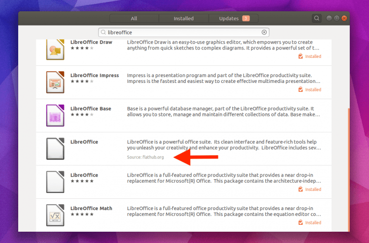
Существует большое количество способов установки Peek. Вы можете это сделать как с помощью snap или flatpak, так и с помощью других источников. Для того, чтобы установить Peek с помощью AppImage воспользуйтесь кнопкой ниже:
Также вы можете использовать официальный PPA-репозиторий для установки. Чтобы сделать это, введите в терминал:
sudo add-apt-repository ppa:peek-developers/stable
sudo apt update && sudo apt install peek
gThumb 3.6.0
На прошлой неделе, также, появилось обновление для давно забытого менеджера фотографий gThumb. С этой версии приложение получает улучшенную поддержку Wayland, ускоренную загрузку фотографий, а также более привлекательный внешний вид (Что было достигнуто благодаря улучшенной поддержке HiDPI).
Другие изменения включают в себя:
- Запуск с помощью двойного щелчка
- Выбор цветов
- Форматирование и фильтрация тегов
- Улучшение вида заголовка
- Панель управления воспроизведением Gif-изображений
- Улучшенный поиск “дубликатов” фотографий
- Постоянная авторизация в Facebook
К сожалению, вы не сможете установить данное приложение через Snap, Flatpak или через любой другой упрощенный способ. Для установки вам придется скачивать исходники, после чего компилировать их. Конечно, в архивах можно отыскать более ранние версии программы, однако очевидно, что они не будут включать в себя все перечисленные изменения и улучшения.
Cozy 0.4.1
Проигрыватель аудиокниг для Linux – Cozy также получил небольшое обновление. Оно включает в себя незначительные изменения пользовательского интерфейса, а также обратную связь для инструмента импорта (в случае, если файл вашей аудио-книги не сможет быть импортирован по какой-то причине, вы будете оповещены сообщением).

Также у Cozy появилась функция поиска, которая позволяет вам искать книги по названию, имени автора, или любому другому ключевому слову.
Загрузить Cozy 0.4.1
Qmmp
В прошлом году был представлен новый медиаплеер с открытым исходным кодом на базе Qt (название расшифровывается как Qt Multi-Media Player). Данное приложение будет особенно интересно фанатам Winamp, т.к имеет схожий интерфейс и функционал.
Вышедший на этих выходных, Qmmp 1.2.0 дебютирует с большим набором улучшений (слишком большим, чтобы перечислять здесь), включая набор новых плагинов, один из которых, кстати говоря, позволяет работать с Icecast.
В общем-то, обо всех остальных изменениях вы можете прочитать по приведенной ссылке. Ну а установить данное приложение можно с помощью PPA, как и всегда, просто добавляем его в список источников и устанавливаем:
sudo add-apt-repository ppa:forkotov02/ppa
sudo apt update && sudo apt install qmmp qmmp-plugin-pack
Другие релизы
Lumina 1.4.0 – графическая оболочка на базе Qt.
VidCutter 5.0 – видеоредактор с открытым исходным кодом.
2017-11-27T13:43:27
Linux