Это самое замечательное время года — для ведения блога. Придайте вашему блогу временную праздничную тему и оправдайте ожидания ваших читателей в светлое и радостное время года.
Небольшие изменения оказывают значительное влияние на посетителей вашего сайта, а WordPress позволяет легко добавить немного сезонного настроения.
Эксперты прогнозируют, что продажи электронной коммерции в праздничные дни вырастут на 16,6% в этом году, так как все больше и больше людей обращают внимание на удобство покупок в Интернете. Установите сцену, добавив немного праздника в свой интернет-магазин, используя эти пять стратегий.
1. Обновите свою тему

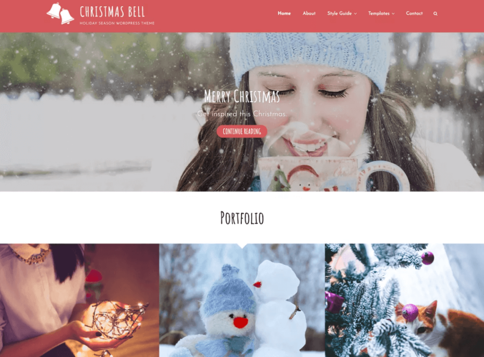
Один из способов поднять настроение вашему сайту — это переключиться на тему праздников до первого года. На WordPress.org есть несколько бесплатных тем, таких как Christmas Bell. Сделайте быстрый поиск, и вы будете удивлены, дома появляется много бесплатных тем. Обязательно найдите тот, который у вас уже есть, так что твики минимальны.
Чтобы загрузить тему, перейдите на панель инструментов WordPress и выберите «Внешний вид»/«Темы»/«Добавить новую». Нажмите «Загрузить» и установите новую тему. Выберите новый дизайн в качестве активной темы, затем дважды проверьте, что все работает правильно.
Красивая тема под праздник должна работать без проблем. Вы потратили много времени на обновление в праздничные дни, поэтому убедитесь, что это положительный опыт для ваших клиентов, который держит их на сайте и не прогоняет их.
2. Добавить украшения

Маленькие украшения добавляют ощущение праздника без особых дополнительных усилий с вашей стороны. Например, вы можете использовать плагин Christmas Ball on Branch для WordPress, чтобы добавить анимированные рождественские детали в угол заголовка вашего блога. Базовая версия бесплатна. Если вы хотите больше контроля над тем, где вы размещаете ветку, доступна профессиональная версия, которая добавляет функции.
Christmas Panda делает что-то похожее, но вы можете добавить деревья, Санта, снегопад или всплывающее окно о Рождестве. Это только два из доступных плагинов, которые позволяют очень легко добавлять украшения. Выполните поиск на WordPress.org или через вкладку «Плагины» на панели инструментов, используя слово «Christmas» или «New Year», и вы найдете множество других вариантов.
Установка плагина аналогична установке темы. Перейдите на панель инструментов и нажмите «Плагины». Нажмите «Добавить новый/Загрузить» и установите его из того места, где вы сохранили плагин. Затем вам нужно будет активировать плагин на вкладке Плагины. Каждый плагин имеет свои настройки, поэтому загляните в инструменты или на вкладку «Плагины», чтобы найти настройки для выбранного вами плагина.
3. Воспроизведение музыки
Куда бы вы ни пошли на каникулах, играет музыка. Если вы попали в торговый центр, Jingle Bells играет в динамиках. Если вы обедаете, мягкое воспроизведение Silent Night играет на заднем плане. Радиостанции постоянно слушают всю рождественскую музыку. Добавьте немного настроения музыки на ваш сайт и он поднимет настроение посетителей в покупках.
Один простой способ добавить музыку — с помощью другого плагина под названием Christmas Music. Этот плагин выбирает песню для вас, но также позволяет вашим посетителям отключить звук одним щелчком мыши. Кнопка отключения — это важная функция, которую можно добавить, если кто-то просматривает ваш сайт во время работы или не хочет воспроизводить музыку, потому что его интернет-соединение немного медленное. Если вы хотите добавить более общую музыку, вы можете использовать плагин, такой как Soundy.
WordPress также имеет встроенный аудиоплеер, который вы можете использовать. Просто добавьте .mp3 или .wav файлы, перейдя в Медиафайлы/Добавить новый и загрузив файл. Как только файл загрузится, посмотрите информацию о вложении справа. Выберите «Вставить медиаплеер», а затем «Вставить в пост».
4. Сделай снег
Какими были бы каникулы без небольшого снега? Вы можете сделать снег на своем сайте с помощью различных плагинов. Некоторые из плагинов, которые делают снег, включая WP Super Snow и Snow. Несколько вещей, которые нужно иметь в виду, включают в себя предложение посетителям отключить падающий снег. Хотя для большинства пользователей снег выпадет без проблем, в случае возникновения проблемы пользователь может отключить эту функцию.
Если вам не нравится идея использования анимации или JavaScript, вы также можете просто изменить фон заголовка на снежное изображение, а затем изменить его после праздников.
5. Украсьте свой логотип
Вы когда-нибудь замечали, что Google меняет свой логотип на разные праздники и особые случаи? Основной шрифт остается прежним, но они могут добавить шляпу Санта-Клауса в одном углу или на небольшом фоне позади букв. Вы можете сделать что-то похожее в праздничные дни, добавив к одной из букв выгравированную снежинку за логотипом или небольшую графику. Сменить логотип в WordPress относительно просто, поэтому его настройка не займет много времени.
Временная тема праздника
Имейте в виду, что идея состоит в том, чтобы добавить временный праздничный дух на ваш сайт. Вам не нужно тратить бесконечные часы на создание уникальной графики.
Другие программисты заложили для вас основу с помощью плагинов, упомянутых выше, а также множеством вариантов бесплатных тем и украшений, которые придают вашему сайту праздничный дух без дополнительной работы.
2018-12-15T19:16:54
Лучшие учебники по Wodpress